Intel D2500HN Product Guide for Intel Desktop Board D2500HN - Page 32
Connecting to the Serial Header, Connecting to the Piezoelectric Speaker Header
 |
View all Intel D2500HN manuals
Add to My Manuals
Save this manual to your list of manuals |
Page 32 highlights
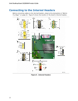
Intel Desktop Board D2500HN Product Guide Connecting to the Serial Header Figure 9, C shows the location of the serial header. Table 8 shows the pin assignments and signal names for the serial header. Table 8. Serial Port Header Pin Signal Name 1 DCD (Data Carrier Detect) 3 TXD# (Transmit Data) 5 Ground 7 RTS (Request To Send) 9 RI (Ring Indicator) Pin Signal Name 2 RXD# (Receive Data) 4 DTR (Data Terminal Ready) 6 DSR (Data Set Ready) 8 CTS (Clear To Send) 10 Key (no pin) Connecting to the Piezoelectric Speaker Header Figure 9, D shows the location of the piezoelectric speaker header. Table 9 shows the pin assignments for the piezoelectric speaker header. Table 9. Piezoelectric Speaker Header Pin Signal Name 1 + 5 VDC 2 Key (no pin) 3 Key (no pin) 4 SPKR 32
-
 1
1 -
2
-
3
-
4
-
5
-
6
-
7
-
8
-
9
-
10
-
11
-
12
-
13
-
14
-
15
-
16
-
17
-
18
-
19
-
20
-
21
-
22
-
23
-
24
-
25
-
26
-
 27
27 -
 28
28 -
 29
29 -
 30
30 -
 31
31 -
 32
32 -
 33
33 -
 34
34 -
 35
35 -
 36
36 -
 37
37 -
38
-
39
-
40
-
41
-
42
-
43
-
44
-
45
-
46
-
47
-
48
-
49
-
50
-
51
-
52
-
53
-
54
-
55
-
56
-
57
-
58
-
59
-
60
 |
 |
