Intel D845HV Product Guide - Page 70
Power and Hardware Connectors, CAUTION
 |
View all Intel D845HV manuals
Add to My Manuals
Save this manual to your list of manuals |
Page 70 highlights
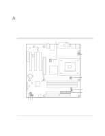
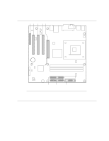
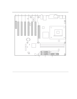
Intel Desktop Boards D845HV and D845WN Product Guide Power and Hardware Connectors CAUTION Failure to use an ATX12V power supply, or not connecting the additional power supply lead to the D845HV or D845WN board may result in damage to the desktop board. The D845HV and D845WN boards require an ATX12V compliant power supply to function according to desktop board specifications. Both boards have two ATX12V compliant power supply connectors that are needed to provide extra power to the Intel 845 chipset and Pentium 4 processor. Figure 21 shows the power and hardware connectors. A 12 34 B 1 1 C 1 1 1 12 D 11 8 9 20 10 1 E H GF Item Description Item Description OM11992 A ATX12V power E Main power B Rear chassis fan (tachometer input) F SCSI hard drive activity LED C Processor fan (tachometer input) G Chassis intrusion D Serial port B H Front chassis fan Figure 21. Power and Hardware Control Connectors 70
-
 1
1 -
2
-
3
-
4
-
5
-
6
-
7
-
8
-
9
-
10
-
11
-
12
-
13
-
14
-
15
-
16
-
17
-
18
-
19
-
20
-
21
-
22
-
23
-
24
-
25
-
26
-
27
-
28
-
29
-
30
-
31
-
32
-
33
-
34
-
35
-
36
-
37
-
38
-
39
-
40
-
41
-
42
-
43
-
44
-
45
-
46
-
47
-
48
-
49
-
50
-
51
-
52
-
53
-
54
-
55
-
56
-
57
-
58
-
59
-
60
-
61
-
62
-
63
-
64
-
 65
65 -
 66
66 -
 67
67 -
 68
68 -
 69
69 -
 70
70 -
 71
71 -
 72
72 -
 73
73 -
 74
74 -
 75
75 -
76
-
77
-
78
-
79
-
80
-
81
-
82
-
83
-
84
-
85
-
86
-
87
 |
 |
