Intel D945GNTL Product Guide - Page 43
Connecting Internal Headers
 |
UPC - 735858174695
View all Intel D945GNTL manuals
Add to My Manuals
Save this manual to your list of manuals |
Page 43 highlights
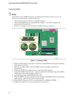
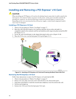
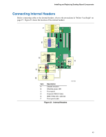
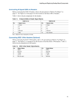
Installing and Replacing Desktop Board Components Connecting Internal Headers Before connecting cables to the internal headers, observe the precautions in "Before You Begin" on page 27. Figure 21 shows the location of the internal headers. Port1L 1 2 GND F Port1R Port2R 34 56 Presence# Sense1_Ret Sense_Send 7 Key (no pin) Port2L 9 10 Sense2_Ret 1394a TPA1+ 1 2 TPA1- Ground 3 4 Ground E TPA2+ 5 6 TPA2- +12 V 7 8 +12 V Key (no pin) 10 Ground USB A USB B Power (+5V) 1 2 Power (+5V) D- 3 4 D- D D+ 5 6 D+ Ground 7 8 Ground Key (no pin) 10 N/C 9 No Connection On/Off 87 Reset 65 C 43 Power LED HD LED 21 A 12 3 B 1 Item A B C D E F Description Chassis intrusion Alternate power LED Front panel Hi-speed USB 2.0 (two) IEEE 1394a (two, optional) Front panel audio Figure 21. Internal Headers OM17620 43
-
 1
1 -
2
-
3
-
4
-
5
-
6
-
7
-
8
-
9
-
10
-
11
-
12
-
13
-
14
-
15
-
16
-
17
-
18
-
19
-
20
-
21
-
22
-
23
-
24
-
25
-
26
-
27
-
28
-
29
-
30
-
31
-
32
-
33
-
34
-
35
-
36
-
37
-
 38
38 -
 39
39 -
 40
40 -
 41
41 -
 42
42 -
 43
43 -
 44
44 -
 45
45 -
 46
46 -
 47
47 -
 48
48 -
49
-
50
-
51
-
52
-
53
-
54
-
55
-
56
-
57
-
58
-
59
-
60
-
61
-
62
-
63
-
64
-
65
-
66
-
67
-
68
-
69
-
70
-
71
-
72
-
73
-
74
 |
 |
