Intel DG35EC Product Specification
Intel DG35EC - Desktop Board Classic Series Motherboard Manual
 |
UPC - 735858200448
View all Intel DG35EC manuals
Add to My Manuals
Save this manual to your list of manuals |
Intel DG35EC manual content summary:
- Intel DG35EC | Product Specification - Page 1
March 2008 Order Number: E35350-001US The Intel® Desktop Board DG35EC may contain design defects or errors known as errata that may cause the product to deviate from published specifications. Current characterized errata are documented in the Intel Desktop Board DG35EC Specification Update. - Intel DG35EC | Product Specification - Page 2
Intel® Desktop Board DG35EC Technical Product Specification Date March 2008 This product specification applies to only the standard Intel® Desktop Board DG35EC with BIOS identifier ECG3510M.86A. Changes to this specification will be published in the Intel Desktop Board DG35EC Specification Update - Intel DG35EC | Product Specification - Page 3
Preface This Technical Product Specification (TPS) specifies the board layout, components, connectors, power and environmental requirements, and the BIOS for the Intel® Desktop Board DG35EC. It describes the standard product and available manufacturing options. Intended Audience The TPS is - Intel DG35EC | Product Specification - Page 4
Intel Desktop Board DG35EC Technical Product Specification Other Common Notation # GB GB/sec Gbit KB Kbit kbits/sec MB MB/sec Mbit Mbit/sec xxh x.x V * Used after a signal name to identify an - Intel DG35EC | Product Specification - Page 5
Feature Summary 10 1.1.2 Board Layout 12 1.1.3 Block Diagram 14 1.2 Legacy Considerations 15 1.3 Online Support 15 1.4 Processor 15 1.5 System Memory 16 1.5.1 Memory Configurations 17 1.6 Intel® G35 Express Chipset 19 1.6.1 Intel G35 Graphics Subsystem 19 1.6.2 USB 21 1.6.3 Serial ATA - Intel DG35EC | Product Specification - Page 6
Features 3.1 Introduction 57 3.2 BIOS Flash Memory Organization 58 3.3 Resource Configuration 58 3.3.1 PCI Autoconfiguration 58 3.3.2 PCI IDE Support 59 3.4 System Management BIOS (SMBIOS 59 3.5 Legacy USB Support 60 3.6 BIOS Updates 61 3.6.1 Language Support 61 3.6.2 Custom Splash Screen - Intel DG35EC | Product Specification - Page 7
for Front Panel USB Headers 49 13. Location of the Jumper Block 50 14. Board Dimensions 51 15. Localized High Temperature Zones 54 Tables 1. Feature Summary 10 2. Board Components Shown in Figure 1 13 3. Supported Memory Configurations 16 4. Audio Jack Support 24 5. LAN Connector LED States - Intel DG35EC | Product Specification - Page 8
Desktop Board DG35EC Environmental Specifications 56 30. BIOS Setup Program Menu Bar 58 31. BIOS Setup Program Function Keys 58 32. AcceptableDrives/Media Types for BIOS Recovery 62 33. Boot Device Menu Options 63 34. Supervisor and User Password Functions 65 35. Beep Codes 67 36. BIOS Error - Intel DG35EC | Product Specification - Page 9
10 1.2 Legacy Considerations 15 1.3 Online Support 15 1.4 Processor 15 1.5 System Memory 16 1.6 Intel® G35 Express Chipset 19 1.7 Parallel IDE Controller 22 1.8 Real-Time Clock Subsystem 23 1.9 Legacy I/O Controller 23 1.10 Audio Subsystem 24 1.11 LAN Subsystem 26 1.12 Hardware Management - Intel DG35EC | Product Specification - Page 10
the major features of the Desktop Board DG35EC. Table 1. Feature Summary Form Factor microATX (9.60 inches by 9.60 inches [243.84 millimeters by 243.84 millimeters]) Processor Memory Chipset Video Support for the following: • Intel® Core™2 Quad processor in an LGA775 socket with a 1333 MHz or - Intel DG35EC | Product Specification - Page 11
• Thermal sense to detect out of range thermal values • Three fan headers • Three fan sense inputs used to monitor fan activity For information about Available configurations for the Desktop Board DG35EC Refer to Section 1.2, page 15 11 - Intel DG35EC | Product Specification - Page 12
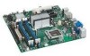
Intel Desktop Board DG35EC Technical Product Specification 1.1.2 Board Layout Figure 1 shows the location of the major components. Figure 1. Major Board Components Table 2 lists the components identified in Figure 1. 12 - Intel DG35EC | Product Specification - Page 13
V Auxiliary front panel power LED header W Front panel USB header X Front panel USB header Y Intel 82801HB I/O Controller Hub (ICH8) Z Intel 82G35 GMCH AA BIOS Setup configuration jumper block BB Battery CC S/PDIF connector DD Front panel audio header Product Description 13 - Intel DG35EC | Product Specification - Page 14
Intel Desktop Board DG35EC Technical Product Specification 1.1.3 Block Diagram Figure 2 is a block diagram of the major functional areas. Figure 2. Block Diagram 14 - Intel DG35EC | Product Specification - Page 15
memory sockets and may require a specialized chassis or cabling solution to use 1.3 Online Support To find information about... Intel Desktop Board DG35EC Desktop Board Support Available configurations for the Desktop Board DG35EC Supported processors Chipset information BIOS and driver updates - Intel DG35EC | Product Specification - Page 16
Intel Desktop Board DG35EC Technical Product Specification # INTEGRATOR'S NOTE Use only ATX12V-compliant power supplies. For information about Power supply connectors Refer to Section 2.2.2.4, page 46 1.5 System Memory The board has four DIMM sockets and supports the following memory features: • - Intel DG35EC | Product Specification - Page 17
mode results in multiple zones of dual and single channel operation across the whole of DRAM memory. To use flex mode, it is necessary to populate both channels. For information about... Memory Configuration Examples Refer to: http://www.intel.com/support/motherboards/desktop/sb/cs011965.htm 17 - Intel DG35EC | Product Specification - Page 18
Intel Desktop Board DG35EC Technical Product Specification Figure 3 illustrates the memory channel and DIMM configuration. NOTE The DIMM 0 sockets of both channels are blue. The DIMM 1 sockets of both channels are black. Figure 3. Memory Channel Configuration and DIMM Configuration # INTEGRATOR'S - Intel DG35EC | Product Specification - Page 19
board's I/O paths. The chipset supports the following features: • Onboard Graphics • Dynamic Video Memory Technology • USB • Serial ATA • Parallel IDE For information about The Intel G35 Express chipset Resources used by the chipset Refer to http://www.intel.com/products/desktop/chipsets/index - Intel DG35EC | Product Specification - Page 20
loaded, the operating system and graphics drivers allocate additional system memory to the graphics buffer as needed for performing graphics functions. NOTE The use of DVMT requires operating system driver support. 1.6.1.3 Configuration Modes The video modes supported by this board are based on the - Intel DG35EC | Product Specification - Page 21
configurations: • Low Voltage Differential Signaling (LVDS) • Single device operating in dual channel mode • HDTV output • HDMI support (when used with the S/PDIF connector) 1.6.2 USB The board supports up to 10 USB 2.0 ports, supports UHCI and EHCI, and uses UHCIand EHCI-compatible drivers - Intel DG35EC | Product Specification - Page 22
Intel Desktop Board DG35EC Technical Product Specification NOTE Many Serial ATA drives use new low 66: DMA protocol on IDE bus supporting host and target throttling and transfer rates of up to 66 MB/sec. ATA-66 protocol is similar to Ultra DMA and is device driver compatible. • ATA-100: DMA protocol - Intel DG35EC | Product Specification - Page 23
CMOS memory. When the computer is not plugged into a wall socket, configuration options for the I/O controller. 1.9.1 Serial Port Interface The serial port header is located on the component side of the board. The serial port supports data transfers at speeds up to 115.2 kbits/sec with BIOS support - Intel DG35EC | Product Specification - Page 24
Intel Desktop Board DG35EC Technical Product Specification 1.9.3 PS/2 Keyboard and Mouse Interface The PS/2 keyboard and mouse connectors are located on the back panel. NOTE The keyboard is supported in the bottom PS/2 connector and the mouse is supported in the top PS/2 connector. Power to the - Intel DG35EC | Product Specification - Page 25
Product Description 1.10.1 Audio Subsystem Software Audio software and drivers are available from Intel's World Wide Web site. For information about Obtaining audio software and drivers Refer to Section 1.2, page 15 1.10.2 Audio Connectors and Headers The board contains audio connectors on the - Intel DG35EC | Product Specification - Page 26
PCI Conventional bus power management ⎯ ACPI technology support ⎯ LAN wake capabilities • LAN subsystem software For information about LAN software and drivers Refer to http://downloadcenter.intel.com 1.11.1 Intel® 82566DC Gigabit Ethernet Controller The Intel 82566DC Gigabit Ethernet Controller - Intel DG35EC | Product Specification - Page 27
1.11.2 LAN Subsystem Software LAN software and drivers are available from Intel's World Wide Web site. For information about Obtaining LAN software and drivers Refer to Section 1.2, page 15 1.11.3 RJ-45 LAN Connector with Integrated LEDs Two LEDs are built into the RJ-45 LAN connector (shown - Intel DG35EC | Product Specification - Page 28
Intel Desktop Board DG35EC Technical Product Specification 1.12 Hardware Management Subsystem The hardware management features enable the board to be compatible with the Wired for Management (WfM) specification. The board the ICH8 • Four thermal sensors (processor, 82G35 GMCH, 82801HB ICH8, and - Intel DG35EC | Product Specification - Page 29
Figure 6 shows the locations of the thermal sensors and fan headers. Item A B C D E F Description Rear chassis fan Thermal diode, located on processor die Processor fan Front chassis fan Thermal diode, located on the ICH8 die Thermal diode, located on the GMCH die Figure 6. Thermal Sensors and - Intel DG35EC | Product Specification - Page 30
Intel Desktop Board DG35EC Technical Product Specification 1.13 Power Management Power management is implemented at several levels, including: • Software support through Advanced Configuration and Power Interface (ACPI) • Hardware support: ⎯ Power connector ⎯ Fan headers ⎯ LAN wake capabilities ⎯ - Intel DG35EC | Product Specification - Page 31
lists the power states supported by the board along with the associated system power targets. See the ACPI specification sleeping state S1 - Processor stopped C1 - stop Service can be performed safely. Notes: 1. Total system power is dependent on the system configuration, including add-in boards - Intel DG35EC | Product Specification - Page 32
requirements. Currently this Intel® Desktop Board meets the Cat B requirements. For information about ENERGY STAR requirements and recommended configurations Refer to http://www.intel.com/go/energystar 1.13.1.3 Wake-up Devices and Events Table 8 lists the devices or specific events that can wake - Intel DG35EC | Product Specification - Page 33
support • WAKE# signal wake-up support LAN wake capabilities and Instantly Available PC technology require power from the +5 V standby line. NOTE The use of Wake from USB from an ACPI state requires an operating system that provides full ACPI support State feature in the BIOS Setup program's Boot - Intel DG35EC | Product Specification - Page 34
Intel Desktop Board DG35EC Technical Product Specification 1.13.2.2 Fan Headers The function/operation of the fan headers is as follows: • The fans are on when the board is in the S0 state. • The fans are off when the board is off or in the S3, S4, or S5 state. • The processor fan header is wired - Intel DG35EC | Product Specification - Page 35
support this specification can participate in power management and can be used to wake the computer. The use of Instantly Available PC technology requires operating system support and PCI 2.3 compliant add-in cards and drivers. 1.13.2.5 Wake from USB USB bus activity wakes the computer from ACPI - Intel DG35EC | Product Specification - Page 36
Intel Desktop Board DG35EC Technical Product Specification 1.13.2.9 +5 V Standby Power Indicator LED The +5 V standby power before installing or removing any devices connected to the board. Failure to do so could damage the board and any attached devices. Figure 7. Location of the Standby Power Indicator - Intel DG35EC | Product Specification - Page 37
55 2.8 Environmental 56 2.1 Memory Map 2.1.1 Addressable Memory The board utilizes 8 GB of addressable system memory. Typically the address space that is allocated for PCI Conventional bus add-in cards, PCI Express configuration space, BIOS (SPI Flash), and chipset overhead resides above the top - Intel DG35EC | Product Specification - Page 38
Intel Desktop Board DG35EC Technical Product Specification The amount of installed memory that can be used will vary based on add-in cards and BIOS settings. Figure 8 shows a schematic of the system memory map. All installed system memory can be used when there is no overlap of system addresses. - Intel DG35EC | Product Specification - Page 39
lists the system memory map. Table 9. System Memory memory Runtime BIOS Reserved Potential available high DOS memory (open to the PCI bus). Dependent on video adapter used. Video memory and BIOS Extended BIOS data (movable by memory manager software) Extended conventional memory Conventional memory - Intel DG35EC | Product Specification - Page 40
Intel Desktop Board DG35EC Technical Product Specification 2.2 Connectors and Headers CAUTION Only the following connectors and headers have overcurrent protection: Back panel and front panel USB, PS/2, and VGA. The other internal connectors/headers are not overcurrent protected and should connect - Intel DG35EC | Product Specification - Page 41
Connectors Figure 9 shows the locations of the back panel connectors. Item A B C D E F G H I J K L Description PS/2 mouse port PS/2 keyboard port VGA port DVI-D port IEEE 1394a port USB ports [2] USB ports [2] LAN USB ports [2] Line in Mic in Line out Figure 9. Back Panel Connectors 41 - Intel DG35EC | Product Specification - Page 42
Intel Desktop Board DG35EC Technical Product Specification 2.2.2 Component-side Connectors and Headers Figure 10 shows the locations of the component-side connectors and headers. Figure 10. Component-side Connectors and Headers 42 - Intel DG35EC | Product Specification - Page 43
10 lists the x16 connector F Rear chassis fan header G Processor core power connector (2 X 2) H Processor fan header I Front chassis fan header J front panel power LED header R Front panel USB header S Front panel USB header T S/PDIF connector U Front panel audio header 43 - Intel DG35EC | Product Specification - Page 44
Intel Desktop Board DG35EC Technical Product Specification 2.2.2.1 Signal Tables for the Connectors and Headers Table 11. Serial ATA Fan Headers Pin Signal Name 1 Control 2 +12 V 3 Tach Table 15. Processor Fan Header Pin Signal Name 1 Ground 2 +12 V 3 FAN_TACH 4 FAN_CONTROL 44 - Intel DG35EC | Product Specification - Page 45
master capable. • SMBus signals are routed to the PCI Conventional bus connector. This enables PCI Conventional bus add-in boards with SMBus support to access sensor data on the board. The specific SMBus signals are as follows: ⎯ The SMBus clock line is connected to pin A40. ⎯ The SMBus data line is - Intel DG35EC | Product Specification - Page 46
Intel Desktop Board DG35EC Technical Product Specification 2.2.2.4 Power Supply Connectors The board has the following power supply connectors: • Main power - a 2 x 12 connector. This connector is compatible with 2 x 10 connectors previously used on Intel Desktop boards. The board supports the use - Intel DG35EC | Product Specification - Page 47
This section describes the functions of the front panel header. Table 21 lists the signal names of the front panel header. Figure 11 is to +5 V 3 HDA# Out Hard disk active LED 4 Reset Switch 5 Ground Ground 6 7 FP_RESET# In Reset switch 8 Power 9 +5 V Power 10 Signal In/ Out - Intel DG35EC | Product Specification - Page 48
Intel Desktop Board DG35EC Technical Product Specification 2.2.2.5.2 Reset Switch Header Pins 5 and 7 can be connected to a momentary single pole, single throw (SPST) type switch that is normally open. When the switch is closed, the board resets and runs the POST. 2.2.2.5.3 Power/Sleep LED - Intel DG35EC | Product Specification - Page 49
12 is a connection diagram for the front panel USB headers. # INTEGRATOR'S NOTES • The +5 V DC power on the front panel USB headers is fused. • Use only a front panel USB connector that conforms to the USB 2.0 specification for high-speed USB devices. Figure 12. Connection Diagram for Front Panel - Intel DG35EC | Product Specification - Page 50
Intel Desktop Board DG35EC Technical Product Specification 2.3 Jumper Block CAUTION Do not move the jumper with the power on. Always turn off the power and unplug the power cord from the computer before changing a jumper setting. Otherwise, the board could be damaged. Figure 13 shows the location of - Intel DG35EC | Product Specification - Page 51
form factor of the board. Dimensions are given in inches [millimeters]. The outer dimensions are 9.60 inches by 9.60 inches [243.84 millimeters by 243.84 millimeters]. Location of the I/O connectors and mounting holes are in compliance with the ATX specification. Figure 14. Board Dimensions 51 - Intel DG35EC | Product Specification - Page 52
Intel Desktop Board DG35EC Technical Product Specification 2.5 Electrical Considerations 2.5.1 Power Supply Considerations CAUTION supported 65 W processor (see Section 1.4 on page 15 for a list of supported processors), 1 GB DDR2 RAM, one hard disk drive, one optical drive, and all board - Intel DG35EC | Product Specification - Page 53
in reduced performance of both the processor and/or voltage regulator or, in some instances, damage to the board. For a list of chassis that have been tested with Intel desktop boards please refer to the following website: http://developer.intel.com/design/motherbd/cooling.htm All responsibility - Intel DG35EC | Product Specification - Page 54
Intel Desktop Board DG35EC Technical Product Specification CAUTION Ensure that proper airflow is maintained in the processor voltage regulator circuit. Failure to do so may result in damage to the voltage regulator circuit. The processor voltage regulator area (shown in Figure 15) can reach a - Intel DG35EC | Product Specification - Page 55
board. Table 28. Thermal Considerations for Components Component Maximum Case Temperature Processor For processor case temperature, see processor datasheets and processor specification updates Intel 82G35 GMCH Intel predicted data at 55 ºC. The Desktop Board DG35EC MTBF is 127,118 hours. 55 - Intel DG35EC | Product Specification - Page 56
Intel Desktop Board DG35EC Technical Product Specification 2.8 Environmental Table 29 lists the environmental specifications for the board. Table 29. Desktop Board DG35EC Environmental Specifications Parameter Specification Temperature Non-Operating Operating -40 °C to +70 °C 0 °C to +55 °C - Intel DG35EC | Product Specification - Page 57
BIOS Flash Memory Organization 58 3.3 Resource Configuration 58 3.4 System Management BIOS (SMBIOS 59 3.5 Legacy USB Support 60 3.6 BIOS Updates 61 3.7 BIOS Recovery 62 3.8 Boot Options 63 3.9 Adjusting Boot Speed 64 3.10 BIOS Security Features 65 3.1 Introduction The board uses an Intel - Intel DG35EC | Product Specification - Page 58
Intel Desktop Board DG35EC Technical Product Specification Table 30 lists the BIOS Setup program menu features. Table 30. BIOS Setup Program Menu Bar Maintenance Main Advanced Security Clears passwords and displays processor information Displays processor and memory configuration Configures - Intel DG35EC | Product Specification - Page 59
connector with independent I/O channel support. The IDE interface supports hard drives up to ATA-66/100 and recognizes any ATAPI compliant devices, including CD-ROM drives, tape drives, and Ultra DMA drives. The BIOS determines the capabilities of each drive and configures them to optimize capacity - Intel DG35EC | Product Specification - Page 60
Intel Desktop Board DG35EC Technical Product Specification 3.5 Legacy USB Support Legacy USB support enables USB devices to be used even when the operating system's USB drivers are not yet available. Legacy USB support is used to access the BIOS Setup program, and to install an operating system that - Intel DG35EC | Product Specification - Page 61
an incompatible BIOS. NOTE Review the instructions distributed with the upgrade utility before attempting a BIOS update. For information about BIOS update utilities Refer to http://support.intel.com/support/motherboards/desktop/s b/CS-022312.htm. 3.6.1 Language Support The BIOS Setup program - Intel DG35EC | Product Specification - Page 62
/ http://developer.intel.com/products/motherboard/dg965wh/tools.htm and http://developer.intel.com/design/motherbd/software.htm 3.7 BIOS Recovery It is unlikely that anything will interrupt a BIOS update; however, if an interruption occurs, the BIOS could be damaged. Table 32 lists the drives and - Intel DG35EC | Product Specification - Page 63
Boot Options In the BIOS Setup program, the user can choose to boot from a diskette drive, hard drive, USB drive, USB flash drive, CD-ROM -ROM is supported in compliance to the El Torito bootable CD-ROM format specification. Under the Boot menu in the BIOS Setup program, ATAPI CDROM is listed as a - Intel DG35EC | Product Specification - Page 64
Intel Desktop Board DG35EC Technical Product Specification 3.9 Adjusting Boot Speed These factors affect system boot speed: • Selecting and configuring peripherals properly • Optimized BIOS boot parameters 3.9.1 Peripheral Selection and Configuration The following techniques help improve system boot - Intel DG35EC | Product Specification - Page 65
Setup program. This is the user mode. • If only the supervisor password is set, pressing the key at the password prompt of the BIOS Setup program allows the user restricted access to Setup. • If both the supervisor and user passwords are set, users can enter either the supervisor password - Intel DG35EC | Product Specification - Page 66
Intel Desktop Board DG35EC Technical Product Specification 66 - Intel DG35EC | Product Specification - Page 67
describing the problem (see Table 35). Table 35. Beep Codes Type Pattern Memory error Three long beeps Thermal warning Four alternating beeps: High tone, low tone, high tone, low tone Frequency 1280 Hz High tone: 2000 Hz Low tone: 1600 Hz 4.3 BIOS Error Messages Table 36 lists the error - Intel DG35EC | Product Specification - Page 68
Intel Desktop Board DG35EC Technical Product Specification 4.4 Port 80h POST Codes During the POST, the BIOS generates diagnostic progress codes (POST codes) to I/O port 80h. If the POST fails, execution stops and the last POST code generated is left at port 80h. This code is useful for determining - Intel DG35EC | Product Specification - Page 69
processor initialization 13 SMM initialization Chipset 21 Initializing a chipset component Memory 22 Reading SPD from memory DIMMs 23 Detecting presence of memory DIMMs 24 Programming timing parameters in the memory controller and the DIMMs 25 Configuring memory 26 Optimizing memory - Intel DG35EC | Product Specification - Page 70
Intel Desktop Board DG35EC Technical Product Specification Table 38. Port 80h POST Codes (continued) POST Code Description of POST Operation Keyboard (PS/2 or USB) 90 Resetting keyboard 91 Disabling keyboard 92 Detecting presence of keyboard 93 Enabling the keyboard 94 Clearing keyboard - Intel DG35EC | Product Specification - Page 71
Error Messages and Beep Codes Table 38. Port 80h POST Codes (continued) POST Code Description of POST Operation DXE Drivers E7 Waiting for user input E8 Checking password E9 Entering BIOS setup EB Calling Legacy Option ROMs Runtime Phase/EFI OS Boot F4 Entering Sleep state F5 Exiting - Intel DG35EC | Product Specification - Page 72
Intel Desktop Board DG35EC Technical Product Specification Table 39. Typical Port 80h POST Sequence POST Code Description 21 Initializing a chipset component 22 Reading SPD from memory DIMMs 23 Detecting presence of memory DIMMs 25 Configuring memory 28 Testing memory 34 Loading - Intel DG35EC | Product Specification - Page 73
standards • European Union Declaration of Conformity statement • Product Ecology statements • Electromagnetic Compatibility (EMC) standards • Product certification markings 5.1.1 Safety Standards Desktop Board DG35EC complies with the safety standards stated in Table 40 when correctly installed in - Intel DG35EC | Product Specification - Page 74
Intel Desktop Board DG35EC Technical Product Specification 5.1.2 European Union Declaration of Conformity Statement We, Intel Corporation, declare under our sole responsibility that the product Intel® Desktop Board DG35EC is in conformity with all applicable essential requirements necessary for CE - Intel DG35EC | Product Specification - Page 75
of this program, including the scope of covered products, available locations, shipping instructions, terms and conditions, etc Intel Product Recycling Program http://www.intel.com/intel/other/ehs/product_ecology Deutsch Als Teil von Intels Engagement für den Umweltschutz hat das Unternehmen das - Intel DG35EC | Product Specification - Page 76
Intel Desktop Board DG35EC Technical Product Specification Español Como parte de su compromiso de responsabilidad medioambiental, Intel ha implantado el programa de reciclaje de productos Intel, que permite que los consumidores al detalle de los productos Intel devuelvan los productos usados en los - Intel DG35EC | Product Specification - Page 77
kayıtlar ve şartlar v.s dahil bütün ayrıntılarını ögrenmek için lütfen http://www.intel.com/intel/other/ehs/product_ecology Web sayfasına gidin. 5.1.3.3 Lead Free Desktop Board This Desktop Board is a European Union Restriction of Hazardous Substances (EU RoHS Directive 2002/95/EC) compliant product - Intel DG35EC | Product Specification - Page 78
Intel Desktop Board DG35EC Technical Product Specification Table 41 shows the various forms of the "Lead-Free 2nd Level Interconnect" mark as it appears on the board and accompanying collateral. Table 41. Lead-Free Board Markings Description Mark Lead-Free 2nd Level Interconnect: This symbol - Intel DG35EC | Product Specification - Page 79
Desktop Board DG35EC complies with the EMC regulations stated in Table 42 when correctly installed in a compatible host system. Table 42. EMC Regulations Regulation Title FCC 47 CFR Part 15, Subpart B Title 47 of the Code . Install and use the equipment according to the instruction manual. 79 - Intel DG35EC | Product Specification - Page 80
Recognized Component mark. Includes adjacent UL file number for Intel desktop boards Intel supplier code number, N-232. Japan VCCI (Voluntary Control Council for Interference) mark. S. Korea MIC (Ministry of Information and Communication) mark. Includes adjacent MIC certification number: CPU-DG35EC - Intel DG35EC | Product Specification - Page 81
Regulatory Compliance and Battery Disposal Information 5.2 Battery Disposal Information CAUTION Risk of explosion if the battery is replaced with an incorrect type. Batteries should be recycled where possible. Disposal of used batteries must be in accordance with local environmental regulations. - Intel DG35EC | Product Specification - Page 82
Intel Desktop Board DG35EC Technical Product Specification PRECAUCIÓN Existe peligro de explosión si la pila no se cambia de forma adecuada. Utilice solamente pilas iguales o del mismo tipo que las recomendadas por - Intel DG35EC | Product Specification - Page 83
Regulatory Compliance and Battery Disposal Information AWAS Risiko letupan wujud jika bateri digantikan dengan jenis yang tidak betul. Bateri sepatutnya dikitar semula jika boleh. Pelupusan bateri terpakai mestilah mematuhi peraturan alam sekitar tempatan. OSTRZEŻENIE Istnieje niebezpieczeństwo - Intel DG35EC | Product Specification - Page 84
Intel Desktop Board DG35EC Technical Product Specification 84
-
 1
1 -
 2
2 -
 3
3 -
 4
4 -
 5
5 -
 6
6 -
 7
7 -
8
-
9
-
10
-
11
-
12
-
13
-
14
-
15
-
16
-
17
-
18
-
19
-
20
-
21
-
22
-
23
-
24
-
25
-
26
-
27
-
28
-
29
-
30
-
31
-
32
-
33
-
34
-
35
-
36
-
37
-
38
-
39
-
40
-
41
-
42
-
43
-
44
-
45
-
46
-
47
-
48
-
49
-
50
-
51
-
52
-
53
-
54
-
55
-
56
-
57
-
58
-
59
-
60
-
61
-
62
-
63
-
64
-
65
-
66
-
67
-
68
-
69
-
70
-
71
-
72
-
73
-
74
-
75
-
76
-
77
-
78
-
79
-
80
-
81
-
82
-
83
-
84
 |
 |

March 2008
Order Number:
E35350-001US
The Intel
®
Desktop Board DG35EC may contain design defects or errors known as errata that may cause the product to deviate from published specifications.
Current
characterized errata are documented in the Intel Desktop Board DG35EC Specification Update.
Intel® Desktop Board
DG35EC
Technical Product Specification