Intel DH55TC Product Guide - Page 48
S/PDIF Header, Parallel Port Header, Table 7. S/PDIF Header Signal Names
 |
View all Intel DH55TC manuals
Add to My Manuals
Save this manual to your list of manuals |
Page 48 highlights
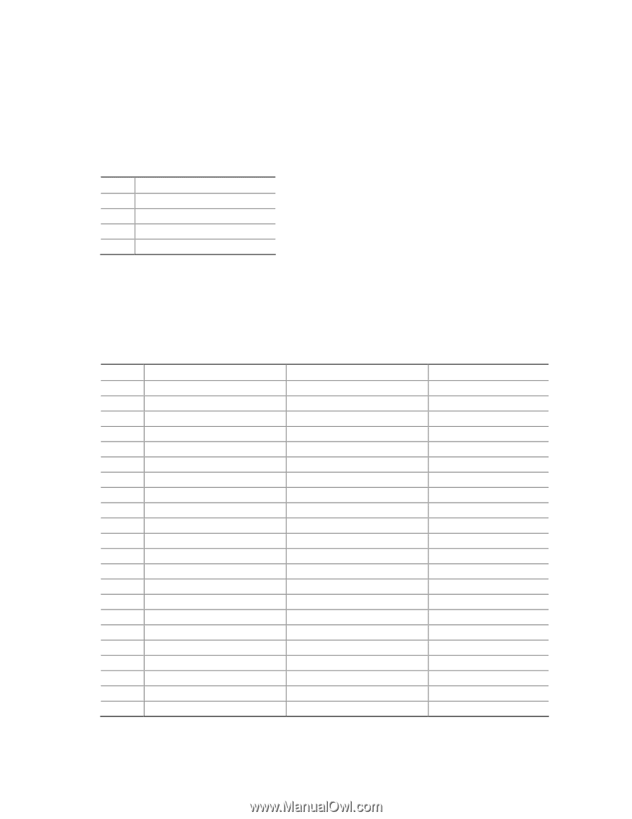
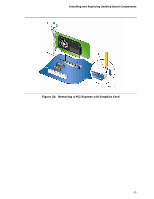
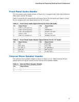
Intel Desktop Board DH55TC Product Guide S/PDIF Header Figure 23, C shows the location of the S/PDIF output header. Table 7 shows the pin assignments and signal names for the S/PDIF output header. Table 7. S/PDIF Header Signal Names Pin Description 1 Ground 2 S/PDIF Out 3 Key (no pin) 4 +5 VDC Parallel Port Header Figure 23, D shows the location of the parallel port header. Table 8 shows the pin assignments and signal names for the parallel port header. Table 8. Parallel Port Header Pin Standard Signal Name 1 STROBE# 2 AUTOFD# 3 PD0 4 FAULT# 5 PD1 6 INT# 7 PD2 8 SLCTIN# 9 PD3 10 GROUND 11 PD4 12 GROUND 13 PD5 14 GROUND 15 PD6 16 GROUND 17 PD7 18 GROUND 19 ACK# 20 GROUND 21 BUSY 22 GROUND ECP Signal Name STROBE# AUTOFD#, HOSACK PD0 FAULT#, PERIPHREQST# PD1 INT#, REVERSERQST# PD2 SLCTIN# PD3 GROUND PD4 GROUND PD5 GROUND PD6 GROUND PD7 GROUND ACK# GROUND BUSY#, PERIPHACK GROUND EPP Signal Name WRITE# DATASTB# PD0 FAULT# PD1 RESET# PD2 ADDRSTB# PD3 GROUND PD4 GROUND PD5 GROUND PD6 GROUND PD7 GROUND INTR GROUND WAIT# GROUND 48
-
 1
1 -
2
-
3
-
4
-
5
-
6
-
7
-
8
-
9
-
10
-
11
-
12
-
13
-
14
-
15
-
16
-
17
-
18
-
19
-
20
-
21
-
22
-
23
-
24
-
25
-
26
-
27
-
28
-
29
-
30
-
31
-
32
-
33
-
34
-
35
-
36
-
37
-
38
-
39
-
40
-
41
-
42
-
 43
43 -
 44
44 -
 45
45 -
 46
46 -
 47
47 -
 48
48 -
 49
49 -
 50
50 -
 51
51 -
 52
52 -
 53
53 -
54
-
55
-
56
-
57
-
58
-
59
-
60
-
61
-
62
-
63
-
64
-
65
-
66
-
67
-
68
-
69
-
70
-
71
-
72
-
73
-
74
-
75
-
76
-
77
-
78
-
79
-
80
-
81
-
82
 |
 |