Intel DH61AG English Product Guide - Page 36
Front Panel Dual-Port USB 2.0 Headers, S/PDIF / DMIC Header
 |
View all Intel DH61AG manuals
Add to My Manuals
Save this manual to your list of manuals |
Page 36 highlights
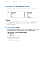
Intel Desktop Board DH61AG Product Guide Front Panel Dual-Port USB 2.0 Headers Figure 16, G shows the location of the front panel dual-port USB 2.0 headers and Table 10 shows their pin assignments and signal names. Table 10. Front Panel Dual-Port USB 2.0 Headers Signal Names Pin Signal Name 1 Power (+5 V) 3 D- 5 D+ 7 Ground 9 Key Pin Signal Name 2 Power (+5 V) 4 D- 6 D+ 8 Ground 10 No Connection NOTE Computer systems that have an unshielded cable attached to a USB port might not meet FCC Class B requirements, even if no device or a low-speed USB device is attached to the cable. Use a shielded cable that meets the requirements for a full-speed USB device. S/PDIF / DMIC Header Figure 16, H shows the location of the S/PDIF / DMIC output header. Table 11 shows the pin assignments and signal names for the S/PDIF / DMIC output header. Table 11. S/PDIF / DMIC Header Signal Names Pin Description 1 3.3 V 2 DMIC_DATA 3 Ground 4 SPDIF_OUT/DMIC_CLK 5 Key (no pin) 6 5 V 36
-
 1
1 -
2
-
3
-
4
-
5
-
6
-
7
-
8
-
9
-
10
-
11
-
12
-
13
-
14
-
15
-
16
-
17
-
18
-
19
-
20
-
21
-
22
-
23
-
24
-
25
-
26
-
27
-
28
-
29
-
30
-
 31
31 -
 32
32 -
 33
33 -
 34
34 -
 35
35 -
 36
36 -
 37
37 -
 38
38 -
 39
39 -
 40
40 -
 41
41 -
42
-
43
-
44
-
45
-
46
-
47
-
48
-
49
-
50
-
51
-
52
-
53
-
54
-
55
-
56
-
57
-
58
-
59
-
60
-
61
-
62
-
63
-
64
-
65
-
66
 |
 |
