Intel E1400 Design Guidelines - Page 62
Recommended Test Sequence, 3.1.2.2, Post-Test Pass Criteria
 |
UPC - 683728187330
View all Intel E1400 manuals
Add to My Manuals
Save this manual to your list of manuals |
Page 62 highlights
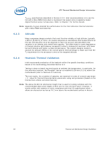
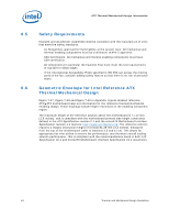
ATX Thermal/Mechanical Design Information Figure 6-5. Shock Acceleration Curve 60 A c c 50 e l 40 e r 30 a t 20 i o n 10 (g) 0 0 2 4 6 8 10 12 Time (m illiseconds) 6.3.1.2.1 Recommended Test Sequence Each test sequence should start with components (i.e., motherboard, heatsink assembly, etc.) that have never been previously submitted to any reliability testing. The test sequence should always start with a visual inspection after assembly, and BIOS/CPU/Memory test (refer to Section 6.3.3). Prior to the mechanical shock & vibration test, the units under test should be preconditioned for 72 hours at 45 ºC. The purpose is to account for load relaxation during burn-in stage. The stress test should be followed by a visual inspection and then BIOS/CPU/Memory test. 6.3.1.2.2 Post-Test Pass Criteria The post-test pass criteria are: 1. No significant physical damage to the heatsink attach mechanism (including such items as clip and motherboard fasteners). 2. Heatsink must remain attached to the motherboard. 3. Heatsink remains seated and its bottom remains mated flatly against IHS surface. No visible gap between the heatsink base and processor IHS. No visible tilt of the heatsink with respect to its attach mechanism. 4. No signs of physical damage on motherboard surface due to impact of heatsink or heatsink attach mechanism. 5. No visible physical damage to the processor package. 6. Successful BIOS/Processor/memory test of post-test samples. 7. Thermal compliance testing to demonstrate that the case temperature specification can be met. 62 Thermal and Mechanical Design Guidelines
-
 1
1 -
2
-
3
-
4
-
5
-
6
-
7
-
8
-
9
-
10
-
11
-
12
-
13
-
14
-
15
-
16
-
17
-
18
-
19
-
20
-
21
-
22
-
23
-
24
-
25
-
26
-
27
-
28
-
29
-
30
-
31
-
32
-
33
-
34
-
35
-
36
-
37
-
38
-
39
-
40
-
41
-
42
-
43
-
44
-
45
-
46
-
47
-
48
-
49
-
50
-
51
-
52
-
53
-
54
-
55
-
56
-
 57
57 -
 58
58 -
 59
59 -
 60
60 -
 61
61 -
 62
62 -
 63
63 -
 64
64 -
 65
65 -
 66
66 -
 67
67 -
68
-
69
-
70
-
71
-
72
-
73
-
74
-
75
-
76
-
77
-
78
-
79
-
80
-
81
-
82
-
83
-
84
-
85
-
86
-
87
-
88
-
89
-
90
-
91
-
92
-
93
-
94
-
95
-
96
-
97
-
98
-
99
-
100
-
101
-
102
-
103
-
104
-
105
-
106
-
107
-
108
-
109
-
110
-
111
-
112
-
113
-
114
-
115
-
116
-
117
-
118
-
119
-
120
-
121
-
122
-
123
-
124
-
125
-
126
-
127
-
128
-
129
-
130
-
131
-
132
-
133
-
134
-
135
-
136
-
137
-
138
-
139
-
140
-
141
-
142
-
143
-
144
-
145
-
146
-
147
-
148
 |
 |
