Intel EM64T User Guide - Page 83
Using 3D Micromanipulator to Secure Bead Location, Measuring Resistance
 |
UPC - 675900697546
View all Intel EM64T manuals
Add to My Manuals
Save this manual to your list of manuals |
Page 83 highlights
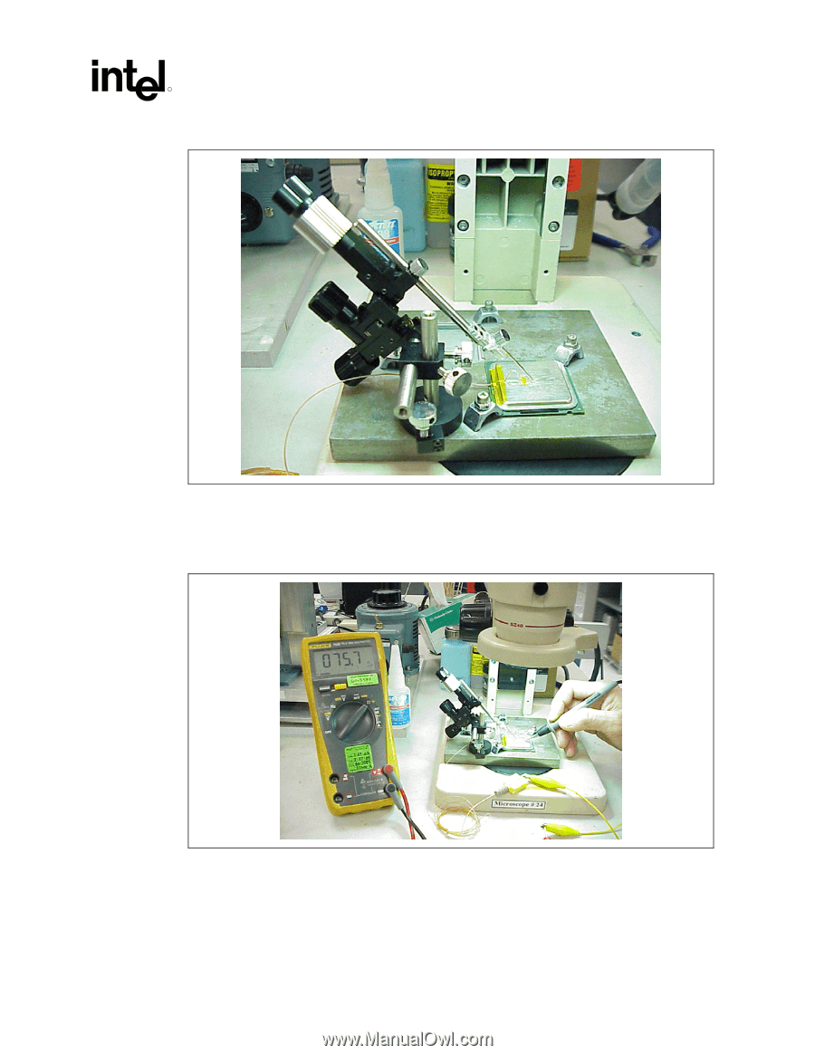
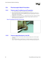
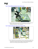
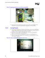
Case Temperature Reference Metrology R Figure 35. Using 3D Micromanipulator to Secure Bead Location 11. Measure resistance from thermocouple end wires (hold both wires to a DMM probe) to the IHS surface. This should be the same value as measured during the thermocouple conditioning see Section D.6.1, step 2 and Figure 36. Figure 36. Measuring Resistance between Thermocouple and IHS 12. Place a small amount of Loctite 498 adhesive in the groove where the bead is installed. Using a fine point device, spread the adhesive in the groove around the needle, the thermocouple bead and the thermocouple wires already installed in the groove during step 5 above. Be careful not to move the thermocouple bead during this step (Figure 37). Thermal/Mechanical Design Guide 83
-
 1
1 -
2
-
3
-
4
-
5
-
6
-
7
-
8
-
9
-
10
-
11
-
12
-
13
-
14
-
15
-
16
-
17
-
18
-
19
-
20
-
21
-
22
-
23
-
24
-
25
-
26
-
27
-
28
-
29
-
30
-
31
-
32
-
33
-
34
-
35
-
36
-
37
-
38
-
39
-
40
-
41
-
42
-
43
-
44
-
45
-
46
-
47
-
48
-
49
-
50
-
51
-
52
-
53
-
54
-
55
-
56
-
57
-
58
-
59
-
60
-
61
-
62
-
63
-
64
-
65
-
66
-
67
-
68
-
69
-
70
-
71
-
72
-
73
-
74
-
75
-
76
-
77
-
 78
78 -
 79
79 -
 80
80 -
 81
81 -
 82
82 -
 83
83 -
 84
84 -
 85
85 -
 86
86 -
 87
87 -
 88
88 -
89
-
90
-
91
-
92
-
93
-
94
-
95
-
96
-
97
-
98
-
99
-
100
-
101
-
102
-
103
-
104
-
105
 |
 |