Intel Q9450 Design Guidelines - Page 26
Package IHS Flatness, Thermal Interface Material - review
 |
UPC - 735858198493
View all Intel Q9450 manuals
Add to My Manuals
Save this manual to your list of manuals |
Page 26 highlights
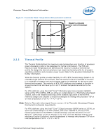
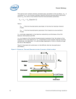
Processor Thermal/Mechanical Information reviewed in depth in the Balanced Technology Extended (BTX) System Design Guide v1.0. Note: The 550g mass limit for ATX solutions is based on the capabilities of the reference design components that retain the heatsink to the board and apply the necessary preload. Any reuse of the clip and fastener in derivative designs should not exceed 550g. ATX Designs that have a mass of greater than 550g should analyze the preload as discussed in Appendix A and retention limits of the fastener. 2.3.3 Package IHS Flatness The package IHS flatness for the product is specified in the datasheet and can be used as a baseline to predict heatsink performance during the design phase. Intel recommends testing and validating heatsink performance in full mechanical enabling configuration to capture any impact of IHS flatness change due to combined socket and heatsink loading. While socket loading alone may increase the IHS warpage, the heatsink preload redistributes the load on the package and improves the resulting IHS flatness in the enabled state. 2.3.4 Thermal Interface Material Thermal interface material application between the processor IHS and the heatsink base is generally required to improve thermal conduction from the IHS to the heatsink. Many thermal interface materials can be pre-applied to the heatsink base prior to shipment from the heatsink supplier and allow direct heatsink attach, without the need for a separate thermal interface material dispense or attach process in the final assembly factory. All thermal interface materials should be sized and positioned on the heatsink base in a way that ensures the entire processor IHS area is covered. It is important to compensate for heatsink-to-processor attach positional alignment when selecting the proper thermal interface material size. When pre-applied material is used, it is recommended to have a protective application tape over it. This tape must be removed prior to heatsink installation. 26 Thermal and Mechanical Design Guidelines
-
 1
1 -
2
-
3
-
4
-
5
-
6
-
7
-
8
-
9
-
10
-
11
-
12
-
13
-
14
-
15
-
16
-
17
-
18
-
19
-
20
-
 21
21 -
 22
22 -
 23
23 -
 24
24 -
 25
25 -
 26
26 -
 27
27 -
 28
28 -
 29
29 -
 30
30 -
 31
31 -
32
-
33
-
34
-
35
-
36
-
37
-
38
-
39
-
40
-
41
-
42
-
43
-
44
-
45
-
46
-
47
-
48
-
49
-
50
-
51
-
52
-
53
-
54
-
55
-
56
-
57
-
58
-
59
-
60
-
61
-
62
-
63
-
64
-
65
-
66
-
67
-
68
-
69
-
70
-
71
-
72
-
73
-
74
-
75
-
76
-
77
-
78
-
79
-
80
-
81
-
82
-
83
-
84
-
85
-
86
-
87
-
88
-
89
-
90
-
91
-
92
-
93
-
94
-
95
-
96
-
97
-
98
-
99
-
100
-
101
-
102
-
103
-
104
-
105
-
106
-
107
-
108
-
109
-
110
-
111
-
112
-
113
-
114
-
115
-
116
-
117
-
118
-
119
-
120
-
121
-
122
-
123
-
124
 |
 |