Intel RS25NB008 User Guide - Page 33
Electrical Characteristics, Table 10. Actual Power Consumption Table
 |
View all Intel RS25NB008 manuals
Add to My Manuals
Save this manual to your list of manuals |
Page 33 highlights
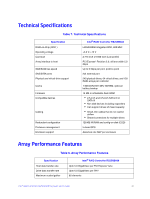
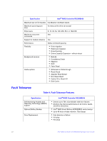
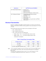
Specification Drive Rebuild Using Hot Spares Error Checking and Indication Intel® RAID Controller RS25NB008 • Automatic at fail • Dedicated per Array • Global for any array • Auto-resume of initialization or rebuild on reboot • Parity generation and checking, automatic consistency checking • Patrol reads • Activity and fault LEDs • Multiple retries • Logs in NVRAM, event log, CIM, Smart, Intel® RAID Web Console 2 Electrical Characteristics All power is supplied to the adapter via the PCI Express 3.3V and 12V rail. Necessary Voltages are provided by onboard switching regulator circuitry operating off of 12V and 3.3V rails. The following states determine the typical current consumption of the board: • State 1. During a hard reset • State 2. During a disk stress test • State 3. While sitting idle at the DOS prompt. - Supply voltage = 12V +/- 8% (from PCI edge connector only) - Supply voltage = 3.3V +/- 9% (from PCI edge connector only) - Actual power consumption. Table 10. Actual Power Consumption Table PCI Edge connector 3.3V supply +12V supply 3.3V AUX. supply (BBU Applications only) State1 330mA 1.00A 30mA State 2 330mA 1.81A 30mA State 3 330mA 1.53A 30mA Note: +12V is used in the charging circuitry for the battery pack on the optional BBU Remote card. If the BBU remote card is cable connected the following power consumption figures apply: 1. During trickle charging of the battery pack: N/A (no trickle charge for Li-ION 2. During fast charging of the battery pack: 250mA rise in +12V current Intel® RAID Controller RS25NB008 Hardware User's Guide 23
-
 1
1 -
2
-
3
-
4
-
5
-
6
-
7
-
8
-
9
-
10
-
11
-
12
-
13
-
14
-
15
-
16
-
17
-
18
-
19
-
20
-
21
-
22
-
23
-
24
-
25
-
26
-
27
-
 28
28 -
 29
29 -
 30
30 -
 31
31 -
 32
32 -
 33
33 -
 34
34 -
 35
35 -
 36
36 -
 37
37 -
 38
38 -
39
-
40
-
41
-
42
-
43
-
44
-
45
-
46
-
47
-
48
-
49
-
50
 |
 |
