Intel S5000VSASATAR User Guide - Page 17
List of s - s5000vsasata server board
 |
View all Intel S5000VSASATAR manuals
Add to My Manuals
Save this manual to your list of manuals |
Page 17 highlights
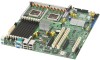
List of Figures Figure 1. Intel® Server Board S5000VSA 1 Figure 2. Server Board Connector and Component Locations 6 Figure 3. Configuration Jumper Descriptions 7 Figure 4. Back Panel Connectors 8 Figure 5. Password Clear Jumper 15 Figure 6. CMOS Clear Jumper 16 Figure 7. Installing Memory (S5000VSASATA/S5000VSASATAR shown 18 Figure 8. Lifting the Socket Handle 20 Figure 9. Open the Load Plate 20 Figure 10. Removing the Shipping Cover 21 Figure 11. Installing the Processor 21 Figure 12. Removing the Protective Socket Cover 21 Figure 13. Installing the Heat Sink 22 Figure 14. Replacing the Backup Battery (S5000VSASATA/S5000VSASATAR shown) ....... 25 Intel® Server Board S5000VSA User's Guide xvii
-
 1
1 -
2
-
3
-
4
-
5
-
6
-
7
-
8
-
9
-
10
-
11
-
 12
12 -
 13
13 -
 14
14 -
 15
15 -
 16
16 -
 17
17 -
 18
18 -
 19
19 -
 20
20 -
 21
21 -
 22
22 -
23
-
24
-
25
-
26
-
27
-
28
-
29
-
30
-
31
-
32
-
33
-
34
-
35
-
36
-
37
-
38
-
39
-
40
-
41
-
42
-
43
-
44
-
45
-
46
-
47
-
48
-
49
-
50
-
51
-
52
-
53
-
54
-
55
-
56
-
57
-
58
-
59
-
60
-
61
-
62
-
63
-
64
-
65
-
66
-
67
-
68
-
69
-
70
-
71
-
72
 |
 |

Intel
®
Server Board S5000VSA User’s Guide
xvii
List of Figures
Figure 1. Intel
®
Server Board S5000VSA
..................................................................................
1
Figure 2. Server Board Connector and Component Locations
.................................................
6
Figure 3. Configuration Jumper Descriptions
............................................................................
7
Figure 4. Back Panel Connectors
..............................................................................................
8
Figure 5. Password Clear Jumper
...........................................................................................
15
Figure 6. CMOS Clear Jumper
................................................................................................
16
Figure 7. Installing Memory (S5000VSASATA/S5000VSASATAR shown)
.............................
18
Figure 8. Lifting the Socket Handle
.........................................................................................
20
Figure 9. Open the Load Plate
................................................................................................
20
Figure 10. Removing the Shipping Cover
...............................................................................
21
Figure 11. Installing the Processor
..........................................................................................
21
Figure 12. Removing the Protective Socket Cover
.................................................................
21
Figure 13. Installing the Heat Sink
..........................................................................................
22
Figure 14. Replacing the Backup Battery (S5000VSASATA/S5000VSASATAR shown)
.......
25