Intel S5520SC Service Guide - Page 10
s, Tables - bios
 |
UPC - 735858207522
View all Intel S5520SC manuals
Add to My Manuals
Save this manual to your list of manuals |
Page 10 highlights
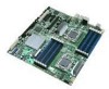
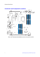
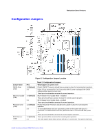
Figures Figures Figure 1. Intel® Workstation Board S5520SC 1 Figure 2. Intel® Workstation Board S5520SC Connector and Component Locations 4 Figure 3. Configuration Jumper Location 5 Figure 4. Back Panel Features ...6 Figure 5. Intel® Light-Guided Diagnostics 8 Figure 6. DIMM Sockets ...10 Figure 7. Intel® SAS Entry RAID Module 15 Figure 8. BIOS Recover Jumper 20 Figure 9. Password Clear Jumper 21 Figure 10. CMOS Clear Jumper 22 Figure 11. Installing Memory ...23 Figure 12. Opening the Processor Socket Lever 25 Figure 13. Opening the Processor Socket Load Plate 25 Figure 14. Removing the Processor Socket Protective Cover 26 Figure 15. Remove Processor Protective Cover 26 Figure 16. Install the processor ...26 Figure 17. Close Load Plate and Socket Lever 27 Figure 18. Installing Processor Heatsink(s 28 Figure 19. Locating Active Heatsink Cable Connections 29 Figure 20. Locating and Removing the CMOS Battery 31 Tables Table 1. Workstation Board Features 1 Table 2. Configuration Jumpers ...5 Table 3. NIC LEDs ...6 Table 4. Storage Mode Matrix ...12 Table 5. Graphics Card Population 14 Table 6. Keyboard Commands ...18 Table 7. Heatsink Requirements for Compatible Intel® Workstation Chassis 27 Table 8. POST Error Beep Codes 32 Table 9. BIOS POST Error Beep Codes 39 Table 10. BMC POST Error Beep Codes 39 Table 11. Product Certification Markings 41 x Intel® Workstation Board S5520SC Service Guide
-
 1
1 -
2
-
3
-
4
-
 5
5 -
 6
6 -
 7
7 -
 8
8 -
 9
9 -
 10
10 -
 11
11 -
 12
12 -
 13
13 -
 14
14 -
 15
15 -
16
-
17
-
18
-
19
-
20
-
21
-
22
-
23
-
24
-
25
-
26
-
27
-
28
-
29
-
30
-
31
-
32
-
33
-
34
-
35
-
36
-
37
-
38
-
39
-
40
-
41
-
42
-
43
-
44
-
45
-
46
-
47
-
48
-
49
-
50
-
51
-
52
-
53
-
54
-
55
-
56
-
57
-
58
-
59
-
60
-
61
-
62
-
63
 |
 |
