Invacare 3GARBASE Owners Manual 2
Invacare 3GARBASE Manual
 |
View all Invacare 3GARBASE manuals
Add to My Manuals
Save this manual to your list of manuals |
Invacare 3GARBASE manual content summary:
- Invacare 3GARBASE | Owners Manual 2 - Page 1
Ranger X™RWD including Power Tilt Only Elevating Seat Only Power Tilt and Elevating Seat 2G Tarsys® (2GT™- Tilt, 2GR™- Recline, 2GTR™- Tilt/Recline) DEALER: This manual MUST be given to the user of the wheelchair. USER: BEFORE using this wheelchair, read this - Invacare 3GARBASE | Owners Manual 2 - Page 2
use this product or any available optional equipment without first completely reading and understanding these instructions and any additional instructional material such as owner's manuals, service manuals or instruction sheets supplied with this product or optional equipment. If you are unable to - Invacare 3GARBASE | Owners Manual 2 - Page 3
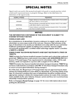
SPECIAL NOTES SPECIAL NOTES Signal words are used in this manual and apply to hazards or unsafe practices which could result in personal injury or property damage. Refer to the table below for definitions of the - Invacare 3GARBASE | Owners Manual 2 - Page 4
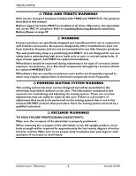
with TRRO and TRBKTS for the purposes described in this manual. Battery support brackets MUST be installed at all times. Otherwise, the wheelchair seating system that is not in this manual, DO NOT perform that procedure. Have the seating system serviced by a qualified technician. ƽ RECLINER WARNINGS - Invacare 3GARBASE | Owners Manual 2 - Page 5
/Power Tilt Only...22 SECTION 1-GENERAL GUIDELINES 24 Repair or Service Information ...24 Accessories Information ...24 Operation Information ...25 Wheelchairs with Manual Recliners Only 27 To Healthcare Professionals/Assistants 27 Tire Pressure ...28 Electrical ...28 Grounding Instructions:...28 - Invacare 3GARBASE | Owners Manual 2 - Page 6
Pinch Points...35 Stairways ...35 Transferring To and From Other Seats 36 SECTION 3-EMI INFORMATION 38 SECTION 4-SAFETY INSPECTION/TROUBLESHOOTING 40 Safety Inspection Checklists...40 All Wheelchairs ...40 Inspect/Adjust Initially...40 Inspect/Adjust Weekly ...41 Inspect/Adjust Monthly ...41 - Invacare 3GARBASE | Owners Manual 2 - Page 7
70° MFX, 90°, PW93, PW93E, PW93ST 64 60° MFX, 70° Taper ...65 PAS4A, 93M, P904A, and PAL4A...65 Adjusting/Replacing Telescoping Front Rigging Support 66 Wheelchairs without 2G Tarsys Systems 66 Wheelchairs with 2G Tarsys Seating Systems 67 Installing Adjustable Angle Flip-up Footplate Hinge 67 - Invacare 3GARBASE | Owners Manual 2 - Page 8
TABLE OF CONTENTS TABLE OF CONTENTS Installing/Removing/Adjusting the Power Elevating Legrests 72 Installing the Power Elevating Legrests 73 Removing the Power Elevating Legrests 73 Adjusting the Power Elevating Legrests 73 Using Mechanical Elevating/Genius Legrests 74 Installing/Removing - Invacare 3GARBASE | Owners Manual 2 - Page 9
TABLE OF CONTENTS TABLE OF CONTENTS Using the Proper Batteries...88 Installing/Removing Batteries Into/From Battery Boxes 89 Disconnecting/Connecting Battery Cables 91 Group 24 Batteries...91 Disconnecting ...91 Connecting ...91 22NF Batteries in Single Battery Box 94 Disconnecting ...94 - Invacare 3GARBASE | Owners Manual 2 - Page 10
WARRANTY 132 REGISTER YOUR PRODUCT The benefits of registering include: 1. Safeguarding your investment. 2. Ensuring long-term maintenance and servicing of your product. 3. Receiving updates with product information, maintenance tips and industry news. Register ONLINE at warranty.invacare.com - Invacare 3GARBASE | Owners Manual 2 - Page 11
LABEL LOCATIONS LABEL LOCATIONS All Wheelchairs NOTE: The battery labels shown on this page and the next are found on the inside of the battery box lids. Group 24 Batteries Only Rear Battery Box Lid Front Battery Box Lid 22NF Batteries Only Gearless Brushless GB™Motors 4 Pole Motors with Group - Invacare 3GARBASE | Owners Manual 2 - Page 12
LABEL LOCATIONS WARNING This stop MUST be in place BEFORE using. DO NOT remove. 1070497 NOTE: Warning label also found on side frame near the rear of the wheelchair. Serial number label is located on the inside of the front or rear frame. Suspension Arm Used with GB Motor Shown Suspension Arm - Invacare 3GARBASE | Owners Manual 2 - Page 13
Wheelchairs with O2 Holders ASBA Seats LABEL LOCATIONS Captain's Seats Wheelchairs with TRRO NOTE: Also on opposite side. NOTE: Also on opposite side. NOTE: Also on opposite side. Wheelchairs without TRRO NOTE: Auto style seat positioning strap shown. This label is also on the airline style - Invacare 3GARBASE | Owners Manual 2 - Page 14
LABEL LOCATIONS Wheelchairs with 2G Tarsys Systems with Genius/Mechanical Legrests Only Systems with Vent Trays Only NOTE: These labels are present on both sides of the seating system. 3G Storm Series® Wheelchairs 14 Part No 1134791 - Invacare 3GARBASE | Owners Manual 2 - Page 15
Wheelchairs with Elevating Seats LABEL LOCATIONS Part No 1134791 15 3G Storm Series® Wheelchairs - Invacare 3GARBASE | Owners Manual 2 - Page 16
OR FOAM FILLED: 8 x 2 inches (Std), 9 x 2¾ inches (Opt) ANTI-TIPPER: 3-inch wheels CASTER FORKS: Standard, Shock Fork (Opt) FOOTRESTS: Telescoping Front Rigging Supports (Std), Swing-Away (Std), Heavy Duty (Opt), 2-in. and 4-in. longer Pivot Slide Tube (Opt) ARMRESTS: Flip Back, Fixed or - Invacare 3GARBASE | Owners Manual 2 - Page 17
TYPICAL PRODUCT PARAMETERS *NOTE: Weight limitation is total weight (user weight plus any additional items that the user may require [back pack, etc.]). Example: If weight limitation of the wheelchair is 300 lbs and additional items equal 25 lbs, subtract 25 lbs from 300 lbs. This means the maximum - Invacare 3GARBASE | Owners Manual 2 - Page 18
fork (Opt) 8 x 2 inches (Std), 9 x 2¾ inches (Opt) ANTI-TIPPER: 3-inch wheels (Std) CASTER FORKS: Standard, Shock Fork (Opt) FOOTRESTS: Telescoping Front Rigging Supports (Std), Swing-Away (Std), Heavy Duty (Opt), 2-in. and 4-in. longer Pivot Slide Tube (Opt) ARMRESTS: Flip Back, Fixed or - Invacare 3GARBASE | Owners Manual 2 - Page 19
TYPICAL PRODUCT PARAMETERS **NOTE: Values for range are calculated for maximum chair weight rating using largest batteries applicable (GP24), per test procedures described in ANSI/RESNA WC/VOL2-1998 Section 4 and meet federal reimbursement requirements for this product. While considered typical, - Invacare 3GARBASE | Owners Manual 2 - Page 20
TYPICAL PRODUCT PARAMETERS RANGER X CASTER FORKS: Standard, Shock Fork (Optional) FOOTRESTS: Telescoping Front Rigging Supports (Std), Swing-Away (Std), Heavy Duty (Opt), 2-in. and 4-in. longer Pivot Slide Tube (Opt) ARMRESTS: Flip Back, Fixed or Adjustable Height (Desk and Full - Invacare 3GARBASE | Owners Manual 2 - Page 21
2G Tarsys TYPICAL PRODUCT PARAMETERS 2G TARSYS SEATING SYSTEM SEAT WIDTH RANGE: 16 - 22 inches in 1-inch increments SEAT DEPTH RANGE: 16 - 22 inches in 1-inch increments BACK HEIGHT RANGE TILT/RECLINE: RECLINE: TILT: 20 - 26 inches in 1-inch increments 20 - 26 inches in 1-inch increments 20 - Invacare 3GARBASE | Owners Manual 2 - Page 22
TYPICAL PRODUCT PARAMETERS **NOTE: Weight limitation is total weight (user weight plus any additional items that the user may require [back pack, etc.]). Example: If weight limitation of the wheelchair is 300 lbs and additional items equal 25 lbs, subtract 25 lbs from 300 lbs. This means the maximum - Invacare 3GARBASE | Owners Manual 2 - Page 23
TYPICAL PRODUCT PARAMETERS WEIGHT OF POWER TILT ONLY: WEIGHT OF ELEVATING SEAT: WEIGHT LIMITATION ELEVATE ONLY: TILT ONLY MOUNTED ON TORQUE SP WITH RANGER II ELECTRONICS: ALL OTHER TILT ONLY SYSTEMS: ELEVATING SEAT/POWER TILT ONLY 65 lbs 26 lbs 300 lbs 200 lbs 250 lbs *NOTE: 20 inch deep x 20 - Invacare 3GARBASE | Owners Manual 2 - Page 24
power OFF, otherwise, injury or damage may occur. Transport ready packages are not retrofittable to existing models and are not field serviceable. Battery support brackets MUST be installed at all times. Otherwise, the wheelchair will not be WC/19 compliant. Refer to Installing/Removing Batteries - Invacare 3GARBASE | Owners Manual 2 - Page 25
SECTION 1-GENERAL GUIDELINES Operation Information Performance adjustments should only be made by professionals of the healthcare field or persons fully conversant with this process and the driver's capabilities. Incorrect settings could cause injury to the driver, bystanders, damage to the - Invacare 3GARBASE | Owners Manual 2 - Page 26
using the wheelchair. If loose, contact a qualified technician for instructions. ALWAYS engage both wheel locks AND reduce the gap distance BEFORE included with TRRO and TRBKTS for the purposes described in this manual. Wheelchairs with Powered Seating Systems Only DO NOT operate the seating - Invacare 3GARBASE | Owners Manual 2 - Page 27
seat. DO NOT attempt to adjust the drive lock-out. Have the wheelchair serviced by a qualified technician. Use only TSS, TRSS, TRCM, and SAC assemblies, otherwise damage to the power legrest may occur. Wheelchairs with Manual Recliners Only NEVER operate the wheelchair while in any recline position - Invacare 3GARBASE | Owners Manual 2 - Page 28
on the side wall of the tire. Electrical Grounding Instructions: DO NOT, under any circumstances, cut or warranty and performance specifications contained in this manual are based on the use of deep charger information prior to installing, servicing or operating your wheelchair. Charging Batteries - Invacare 3GARBASE | Owners Manual 2 - Page 29
. DO NOT sit in the wheelchair while charging the batteries. READ and CAREFULLY follow the manufacturer's instructions for each charger (supplied or purchased). If charging instructions are not supplied, consult a qualified technician for proper procedures. Ensure the pins of the extension cord - Invacare 3GARBASE | Owners Manual 2 - Page 30
SECTION 1-GENERAL GUIDELINES Front of Wheelchair Rear of Wheelchair Base Frame Frame End Cap Weight Limitation 3G Storm Wheelchairs without Powered Seating Systems Refer to Typical Product Parameters for Arrow on page 16, Torque SP on page 17 or Ranger X on page 19 to determine the weight limit - Invacare 3GARBASE | Owners Manual 2 - Page 31
the close attention of the wheelchair user as well as the assistant. This manual points out the most common procedures and techniques involved in the safe operation architectural barriers. Use this information only as a "basic" guide. The techniques that are discussed on the following pages have - Invacare 3GARBASE | Owners Manual 2 - Page 32
impediments. Also, be aware of detachable parts such as arms or legrests. These must NEVER be used to move the wheelchair or as lifting supports, as they may be inadvertently released, resulting in possible injury to the user and/or assistant(s). When learning a new assistance technique, have an - Invacare 3GARBASE | Owners Manual 2 - Page 33
SECTION 2-SAFETY/HANDLING OF WHEELCHAIRS NOTE: For this procedure, refer to FIGURE 2.1. Changing the position of where the motors are positioned affects the weight distribution over the rear wheels. The following contains information about changing the position of the motors. Rear Position - - Invacare 3GARBASE | Owners Manual 2 - Page 34
SECTION 2-SAFETY/HANDLING OF WHEELCHAIRS Reaching, Leaning and Bending - Forward ƽ WARNING DO NOT attempt to reach objects if you have to move forward in the seat or pick them up from the floor by reaching down between your knees. Inasmuch as wheel locks are an option on this wheelchair, (You may - Invacare 3GARBASE | Owners Manual 2 - Page 35
or down the stairs. Invacare recommends using two assistants and making thorough preparations. Make sure to use ONLY secure, non-detachable parts for hand-hold supports. DO NOT attempt to lift the wheelchair by any removable (detachable) parts. Lifting by means of any removable (detachable) parts of - Invacare 3GARBASE | Owners Manual 2 - Page 36
SECTION 2-SAFETY/HANDLING OF WHEELCHAIRS Follow this procedure for moving the wheelchair between floors when an elevator is NOT available: NOTE: When using a stairway to move the wheelchair and any accessories, move all wheelchair components away from the stairway prior to reassembly. 1. Remove the - Invacare 3GARBASE | Owners Manual 2 - Page 37
SECTION 2-SAFETY/HANDLING OF WHEELCHAIRS 3. Shift body weight into seat with transfer. NOTE: During independent transfer, little or no seat platform will be beneath you. Use a transfer board if at all possible. Minimize Gap Distance FIGURE 2.5 Transferring To and From Other Seats Part No 1134791 - Invacare 3GARBASE | Owners Manual 2 - Page 38
, CD players, cassette players, and small appliances, such as electric shavers and hair dryers, so far as we know, are not likely to cause EMI problems to your powered wheelchair. 3G Storm Series® Wheelchairs 38 Part No 1134791 - Invacare 3GARBASE | Owners Manual 2 - Page 39
SECTION 3-EMI INFORMATION ƽ WARNING Powered Wheelchair Electromagnetic Interference (EMI) Because EM energy rapidly becomes more intense as one moves closer to the transmitting antenna (source), the EM fields from hand-held radio wave sources (transceivers) are of special concern. It is possible to - Invacare 3GARBASE | Owners Manual 2 - Page 40
SECTION 4-SAFETY INSPECTION/TROUBLESHOOTING SECTION 4-SAFETY INSPECTION/ TROUBLESHOOTING NOTE: Every six months take your wheelchair to a qualified technician for a thorough inspection and servicing. Regular cleaning will reveal loose or worn parts and enhance the smooth operation of your wheelchair - Invacare 3GARBASE | Owners Manual 2 - Page 41
SECTION 4-SAFETY INSPECTION/TROUBLESHOOTING ❑ Make sure wheel locks are easy to engage. ❑ Inspect tires for flat spots and wear. ❑ Check pneumatic tires for proper inflation. ❑ Check power center mount - Invacare 3GARBASE | Owners Manual 2 - Page 42
SECTION 4-SAFETY INSPECTION/TROUBLESHOOTING ❑ Make sure wheel locks are easy to engage. ❑ Ensure that casters are free of debris. ❑ Check power center mount front riggings for worn/frayed belts - Invacare 3GARBASE | Owners Manual 2 - Page 43
SECTION 4-SAFETY INSPECTION/TROUBLESHOOTING ❑ Make sure elevate systems drive with reduced speed when seat is in elevated position (Elevating Seat Only). ❑ Check that spreader bar mounting fasteners are tight ( - Invacare 3GARBASE | Owners Manual 2 - Page 44
Troubleshooting - Electrical NOTE: For additional troubleshooting information and explanation of error codes, refer to the individual Electronics Manual 100). Malfunctioning battery charger. Contact Dealer/Invacare for Service. Electrical malfunction. Battery indicator flashes the charge level - Invacare 3GARBASE | Owners Manual 2 - Page 45
4-SAFETY INSPECTION/TROUBLESHOOTING SYMPTOM Joystick for Service. Contact Dealer/Invacare for Service. Reprogram controller. (Refer to electronics manual supplied on page 50. Contact Invacare/Dealer for service if this does not solve the problem. Seating system is elevated. Return joystick to - Invacare 3GARBASE | Owners Manual 2 - Page 46
4-SAFETY INSPECTION/TROUBLESHOOTING Checking Battery Charge Level The following "Do's" and "Don'ts" are provided for your convenience and safety. DON'T DO Don't perform any installation or maintenance without first reading this manual. Read and understand this manual and any service information - Invacare 3GARBASE | Owners Manual 2 - Page 47
SECTION 5-WHEELCHAIR OPERATION SECTION 5-WHEELCHAIR OPERATION ƽ WARNING After ANY adjustments, repair or service and BEFORE use, make sure that all attaching hardware is tightened securely - otherwise injury or damage may result. Set-up of the Electronic Control Unit - Invacare 3GARBASE | Owners Manual 2 - Page 48
SECTION 5-WHEELCHAIR OPERATION Using the Joystick to Drive the Wheelchair The joystick is located at the front of the joystick housing and provides smooth control of speed and direction. It is equipped with 360 degrees of mobility for ease of operation. The joystick is spring-loaded, and - Invacare 3GARBASE | Owners Manual 2 - Page 49
vertical position, DO NOT operate the wheelchair or elevate/lower the seat. DO NOT attempt to adjust the drive lock-out. Have the wheelchair serviced by a qualified technician. The wheelchair user MUST have a clear line of sight to drive safely. On initial wheelchair delivery and after adjusting the - Invacare 3GARBASE | Owners Manual 2 - Page 50
the vertical position, DO NOT operate the wheelchair or elevate/lower the seat. DO NOT attempt to adjust the drive lock-out. Have the wheelchair serviced by a qualified technician. DO NOT operate the seating system while on an incline. DO NOT operate seating system while the wheelchair is moving. DO - Invacare 3GARBASE | Owners Manual 2 - Page 51
SECTION 5-WHEELCHAIR OPERATION ƽ ACTUATOR CONTROL WARNING Use only the actuator controls listed in the following chart to activate the tilt/ recline/elevate functions. DO NOT USE any other actuator controls. Such devices may result in excess heating and cause damage to the actuator and associated - Invacare 3GARBASE | Owners Manual 2 - Page 52
has been released to the neutral position for a minimum of five seconds. Refer to the Electronics Service Manual listed in Reference Documents on page 2 for complete four-way toggle switch operating instructions. **NOTE: The seat MUST be tilted/reclined so the back angle is less than 20° relative - Invacare 3GARBASE | Owners Manual 2 - Page 53
has been released to the neutral position for a minimum of five seconds. Refer to the Electronics Service Manual listed in Reference Documents on page 2 for complete four-way toggle switch operating instructions. **NOTE: The seat MUST be tilted/reclined so the back angle is less than 20° relative - Invacare 3GARBASE | Owners Manual 2 - Page 54
has been released to the neutral position for a minimum of five seconds. Refer to the Electronics Service Manual listed in Reference Documents on page 2 for complete four-way toggle switch operating instructions. **NOTE: The seat MUST be tilted/reclined so the back angle is less than 20° relative - Invacare 3GARBASE | Owners Manual 2 - Page 55
device in the corresponding "left" direction to operate the tilt function. Refer to the Electronics Service Manual listed in Reference Documents on page 2 for complete switch option operating instructions. 4. Return the back to the position noted in STEP 2 before changing the degree of recline - Invacare 3GARBASE | Owners Manual 2 - Page 56
SECTION 5-WHEELCHAIR OPERATION MKIV-A Joystick Switches and Indicators NOTE: For this procedure, refer to FIGURE 5.4 on page 56. Drive Select/On/Off Switch A three position toggle switch is located at the back of the joystick housing. The Drive Select position is momentary. This switch allows the - Invacare 3GARBASE | Owners Manual 2 - Page 57
on and off to indicate the type of fault detected. A chart of the diagnostic indications is given in the Diagnostic Code Section of the electronics manual, part number 1043576. Mode and Level Indicators Two LED indicators are located on either side of the battery bar graph display. The Mode light - Invacare 3GARBASE | Owners Manual 2 - Page 58
SECTION 5-WHEELCHAIR OPERATION MODE RIM LEVEL INDICATOR Off On MEANING Wheelchair moves forward when forward command is given. Wheelchair moves in reverse when forward command is given. Emergency Stop Reset Switch NOTE: For this procedure, refer to FIGURE 5.5. The emergency stop switch is used - Invacare 3GARBASE | Owners Manual 2 - Page 59
on the left side at the rear of the joystick housing. This switch is used to program the wheelchair. Refer to the electronics manual, part number 1043576, for more information about programming the wheelchair. Joystick Proportional drive control knob located at the front of the joystick housing - Invacare 3GARBASE | Owners Manual 2 - Page 60
SECTION 5-WHEELCHAIR OPERATION LCD Display Located in front of the joystick, it provides information on the status of the wheelchair through a two line by twelve character length back lighted display. The LCD display is easily readable in both bright sunlight and complete darkness. During normal - Invacare 3GARBASE | Owners Manual 2 - Page 61
SECTION 5-WHEELCHAIR OPERATION • Pneumatic Control • Stand-by Mode • RIM Control • Remote Drive Selection Mode • Information Center Display Selection (does not require Reset activation at power up) If any of the above modes are selected, the control will require activation of the switch immediately - Invacare 3GARBASE | Owners Manual 2 - Page 62
Green flashes will indicate the type of fault detected. A chart of the diagnostic indications is given in the Diagnostic Code Section of the Electronics manual, part number 1095272. NOTE: When reading the Battery Discharge Indicator (BDI), the joystick MUST be in the Neutral position for an accurate - Invacare 3GARBASE | Owners Manual 2 - Page 63
SECTION 6-FRONT RIGGINGS SECTION 6-FRONT RIGGINGS ƽ WARNING After ANY adjustments, repair or service and BEFORE use, make sure that all attaching hardware is tightened securely - otherwise injury or damage may result. While the wheelchair is moving, minimum ground - Invacare 3GARBASE | Owners Manual 2 - Page 64
on a flat surface to simplify this section. 3. Remove the mounting screw, washers and locknut that secure the lower footrest to the footrest support. 4. Reposition the lower footrest to the desired height. 5. Reinstall the mounting, washers and locknut that secure the lower footrest to the footrest - Invacare 3GARBASE | Owners Manual 2 - Page 65
: For this procedure, refer to FIGURE 6.5. 1. Loosen, but DO NOT remove the lug bolt and locknut that secure the lower footrest to the footrest support. 2. Reposition the lower footrest to the desired height. 3. Securely tighten the lug bolt and locknut that secure the lower footrest to the footrest - Invacare 3GARBASE | Owners Manual 2 - Page 66
and threaded blocks securing the telescoping front tube to the side rail. 2. Perform one of the following: • Slide existing telescoping front rigging support to one of six depth positions. • Remove existing telescoping front rigging. 3. Secure the telescoping front tube to the side rail at the - Invacare 3GARBASE | Owners Manual 2 - Page 67
NOTE: The footplate hinge will fall to the Down position. 4. Tighten the mounting screw, washer, and locknut that secure the footplate hinge to the footrest support until the footplate hinge remains in the Up position. 5. Check the up and down motion of the footplate hinge to make sure the user of - Invacare 3GARBASE | Owners Manual 2 - Page 68
Observe the angle of the articulating footplate for reinstallation. 2. Move articulating footplate to one of four mounting positions. 90° Footrest Support Flat Screws Articulating Footplate Footplate Hinge Nylon Adjustment Screw NOTE: If desired depth is still not obtained, rotate the half clamp - Invacare 3GARBASE | Owners Manual 2 - Page 69
to perform this adjustment. 1. Insert a flathead screwdriver through the half clamp on the articulating footplate. Footrest Support Footplate Front View Of Footplate and Footrest Support 2. Slowly turn nylon adjustment screw in or out until articulating footplate is perpendicular to the footrest - Invacare 3GARBASE | Owners Manual 2 - Page 70
SECTION 6-FRONT RIGGINGS Reassembly 1. Replace heel strap/loop. 2. Reverse preceding steps to reassemble. NOTE: When securing heel loop to the footrest assembly, tighten mounting screw until the spacer is secure. Composite Mounting Screw Spacer Composite Footplate Locknut Articulating Mounting - Invacare 3GARBASE | Owners Manual 2 - Page 71
Elevating Legrests 1. Perform one of the following: • Raising - Pull back on the release lever until the leg is at the desired height. • Lowering - Support leg with one hand and push release lever downward with other hand. Adjusting Calfpads 1. Turn the calfpad towards the outside of the wheelchair - Invacare 3GARBASE | Owners Manual 2 - Page 72
SECTION 6-FRONT RIGGINGS Legrest to Normal Position Adjust Calfpad Secure Calfpad FIGURE 6.14 Raising/Lowering Elevating Legrests and/or Adjusting Calfpads Installing/Removing/Adjusting the Power Elevating Legrests ƽ WARNING To prevent personal injury, always verify proper positioning of legs and - Invacare 3GARBASE | Owners Manual 2 - Page 73
SECTION 6-FRONT RIGGINGS Installing the Power Elevating Legrests NOTE: For this procedure, refer to FIGURE 6.15. 1. Turn power legrest to side (open footplate is perpendicular to wheelchair). Refer to Detail "A" of FIGURE 6.15. 2. Insert the mounting pin of power legrest into the mounting hole of - Invacare 3GARBASE | Owners Manual 2 - Page 74
SECTION 6-FRONT RIGGINGS CONTROLLER TRCM version 2.2 or earlier TAC version 1.1 or earlier TRCM version 2.3 or higher TAC version 1.11 or higher LEG UP SPEED 70% or higher 40% or higher LEG DOWN SPEED 50% or higher 35% or higher Using Mechanical Elevating/Genius Legrests CAUTION DO NOT operate - Invacare 3GARBASE | Owners Manual 2 - Page 75
SECTION 6-FRONT RIGGINGS 4. Lift the elevating legrest up and position the mechanical elevating legrest push rod around the pin on the legrest as shown in FIGURE 6.17. 5. Press down on mechanical elevating legrest push rod until there is an audible "click". 6. Repeat STEPS 1-5 for the opposite - Invacare 3GARBASE | Owners Manual 2 - Page 76
height cannot be adjusted independently of the recline function of the wheelchair. If the mechanical elevating legrests are not operating as desired, have the wheelchair serviced by an Invacare dealer or technician. 3G Storm Series® Wheelchairs 76 Part No 1134791 - Invacare 3GARBASE | Owners Manual 2 - Page 77
SECTION 6-FRONT RIGGINGS Adjusting Genius Legrests NOTE: These procedures apply to wheelchairs with 2G Tarsys seating systems only. Footplate Height NOTE: For this procedure, refer to FIGURE 6.20. 1. Note the angle of the footplate in relation to the legrest as shown in FIGURE 6.20. 2. Loosen, but - Invacare 3GARBASE | Owners Manual 2 - Page 78
Legrest Height NOTE: For this procedure, refer to FIGURE 6.22. 1. Remove the button screw that secures the adjustment link and two washers to the legrest support. 2. Move adjustment link to one of three positions. 3. Line up the two washers and adjustment link with the mounting hole in the legrest - Invacare 3GARBASE | Owners Manual 2 - Page 79
SECTION 7-ARMS SECTION 7-ARMS ƽ WARNING After ANY adjustments, repair or service and BEFORE use, make sure that all attaching hardware is tightened securely - otherwise injury or damage may result. Installing/Removing Flip Back Armrests ƽ WARNING Make - Invacare 3GARBASE | Owners Manual 2 - Page 80
SECTION 7-ARMS Flip Back Armrest Locked (Vertical) Rear Arm Socket Quick Release Pin Seat Frame Unlocked (Horizontal) Flip Back Armrest Release Lever Front Arm Socket FIGURE 7.1 Installing/Removing Flip Back Armrests Adjusting Flip Back Armrests ƽ WARNING Make sure the flip back armrest - Invacare 3GARBASE | Owners Manual 2 - Page 81
Adjusting 1. Unlock top of flip back armrest by pulling height adjustment lever into the up (horizontal) position. 2. Adjust top of the flip back armrest to the desired height. 3. Lock top of flip back armrest by pushing height adjustment lever into the down (vertical) position. SECTION 7-ARMS - Invacare 3GARBASE | Owners Manual 2 - Page 82
SECTION 7-ARMS Height NOTE: For this procedure, refer to FIGURE 7.4. 1. Remove the mounting screw that secures the armrest to the van seat frame. 2. Adjust the armrest to one of four positions. 3. Reinstall the mounting screw that secures the armrest to the van seat frame and tighten securely. - Invacare 3GARBASE | Owners Manual 2 - Page 83
SECTION 7-ARMS Adjusting Reclining Armrest Height NOTE: For this procedure, refer to FIGURE 7.6. NOTE: This procedure applies to 2G Tarsys seating systems only. 1. Make sure the seating system is in the full upright position. Refer to Operating Powered Seating Systems on page 50. 2. Remove the - Invacare 3GARBASE | Owners Manual 2 - Page 84
SECTION 8-POSITIONING STRAP SECTION 8-POSITIONING STRAP ƽ WARNING After ANY adjustments, repair or service and BEFORE use, make sure that all attaching hardware is tightened securely - otherwise injury or damage may result. The seat positioning strap is a positioning belt - Invacare 3GARBASE | Owners Manual 2 - Page 85
Mounting Holes SECTION 8-POSITIONING STRAP Seat Frame Mounting Screw Seat Frame Locknuts Quick-Release Pin Tab Mounting Screw Washers Quick-Release Pin Tab Seat Positioning Strap Halves FIGURE 8.1 Replacing Seat Positioning Strap - Wheelchairs without 2G Tarsys Seating Systems or TRRO - Invacare 3GARBASE | Owners Manual 2 - Page 86
SECTION 9-VAN SEAT SECTION 9-VAN SEAT ƽ WARNING After ANY adjustments, repair or service and BEFORE use, make sure that all attaching hardware is tightened securely - otherwise injury or damage may result. Adjusting Van Seat Angle NOTE: For this - Invacare 3GARBASE | Owners Manual 2 - Page 87
SECTION 10-BATTERIES SECTION 10-BATTERIES Warnings for Handling and Replacing Batteries ƽ WARNING After ANY adjustments, repair or service and BEFORE use, make sure all attaching hardware is tightened securely - otherwise injury or damage may occur. Make sure power to the wheelchair is OFF - Invacare 3GARBASE | Owners Manual 2 - Page 88
SECTION 10-BATTERIES Using the Proper Batteries 1. Place battery on ground/flat surface. 2. Visually inspect the battery to ensure the correct position of the POSITIVE and NEGATIVE terminals: ƽ WARNING FOR WHEELCHAIRS WITH 22NF BATTERIES Batteries with terminal configuration (POSITIVE on the left - Invacare 3GARBASE | Owners Manual 2 - Page 89
SECTION 10-BATTERIES ƽ WARNING FOR WHEELCHAIRS THAT USE GP24 BATTERIES Batteries with terminal configuration (POSITIVE on the right and NEGATIVE on the left) as shown below MUST be used. Batteries that have the reverse terminal configuration MUST not be used - otherwise injury and damage may occur. - Invacare 3GARBASE | Owners Manual 2 - Page 90
the life of the battery. DO NOT tip the batteries. Keep the batteries in an upright position. The warranty and performance specifications contained in this manual are based on the use of deep cycle gel cell batteries. Invacare strongly recommends their use as the power source for this unit. CAUTION - Invacare 3GARBASE | Owners Manual 2 - Page 91
SECTION 10-BATTERIES Disconnecting/Connecting Battery Cables ƽ WARNING NEVER allow any of your tools and/or battery cable(s) to contact BOTH battery post(s) at the same time. An electrical short may occur and serious personal injury or damage may occur. The use of rubber gloves and safety glasses is - Invacare 3GARBASE | Owners Manual 2 - Page 92
SECTION 10-BATTERIES 4. Install the locknut and fuse mounting screw to connect the RED battery cable to the POSITIVE (+) battery post (Detail "A" of FIGURE 10.2). 5. Verify battery cables are correctly installed and securely tightened. NOTE: Cables will be crossed on one connector battery box top. - Invacare 3GARBASE | Owners Manual 2 - Page 93
SECTION 10-BATTERIES DETAIL "A" - CONNECTING CABLES TO TERMINALS Top View of Battery Mounting Screw Locknut Locknut POSITIVE (+) Battery Terminal/Post NEGATIVE (-) Battery Terminal/Post Black NEGATIVE (-) Battery Cable Fuse Mounting Screw RED POSITIVE (+) Battery Cable Two Connector Battery - Invacare 3GARBASE | Owners Manual 2 - Page 94
SECTION 10-BATTERIES 22NF Batteries in Single Battery Box NOTE: For this procedure, refer to FIGURE 10.3 on page 95. NOTE: Note polarity of white battery cable (jumper) battery terminal ends. Disconnecting 1. Remove battery terminal cap(s) from battery terminal(s) ends. Refer to Detail A" in FIGURE - Invacare 3GARBASE | Owners Manual 2 - Page 95
P N WHITE Battery Cable (Jumper) Front Battery Single Battery Box Bottom Rear Battery STEP 2 FRONT REAR SECTION 10-BATTERIES Front Battery STEPS 3 and 4 FRONT Rear Battery RED POSITIVE (+) Battery Cable Battery Box Bottom NEGATIVE (-) Battery Terminal/Post BLACK NEGATIVE (-) Battery Cable - Invacare 3GARBASE | Owners Manual 2 - Page 96
SECTION 10-BATTERIES When to Charge Batteries NOTE: For this procedure, refer to FIGURE 10.4. MKIV-A and MKIV-RII Joysticks The Battery Discharge Indicator (BDI) is a bar graph display located on the MKIV joystick. It will keep you informed as to power availability. A visual warning is given before - Invacare 3GARBASE | Owners Manual 2 - Page 97
sections independently, read and carefully follow the individual instructions for each charger (supplied or purchased). NOTE: If charging instructions are not supplied, consult a qualified service technician for proper instructions. NOTE: Have the following tools available: • Battery Charger - Invacare 3GARBASE | Owners Manual 2 - Page 98
batteries need to be charged more often or take longer to charge than normal, they may need to be replaced. Contact an Invacare dealer for service. 3G Storm Series® Wheelchairs 98 Part No 1134791 - Invacare 3GARBASE | Owners Manual 2 - Page 99
Battery Charger Mount Bracket Base Frame Battery Charger Front View of Joystick From Battery Charger Charger Port Joystick Battery Boxes Charger Port Three Pronged Plug Support Plate Battery Charger Port Part No 1134791 FIGURE 10.5 Charging Batteries 99 3G Storm Series® Wheelchairs - Invacare 3GARBASE | Owners Manual 2 - Page 100
size and/or voltage may cause damage to your wheelchair and give you unsatisfactory performance. The warranty and performance specifications contained in this manual are based on the use of deep cycle gel cell batteries. Invacare strongly recommends their use as the power source for this unit - Invacare 3GARBASE | Owners Manual 2 - Page 101
SECTION 10-BATTERIES Cleaning Battery Terminals ƽ WARNING Most batteries are not sold with instructions. However, warnings are frequently noted on the cell caps. Read them carefully. DO NOT allow the liquid in the battery to come in contact with - Invacare 3GARBASE | Owners Manual 2 - Page 102
top of the battery box and will not interfere with the one battery box guide pins when engaging the connector on the one battery box lid. 6. Secure the . 8. Slide one connector battery box along the sub-frame until its guide pins are engaged in the connector of the two connector battery box. NOTE - Invacare 3GARBASE | Owners Manual 2 - Page 103
on head portion of the mounting screws that secure the shocks to the base frame. ƽ WARNING Wheelchairs with TRRO or TRBKTS Only - Battery support brackets MUST be installed at all times. Otherwise, the wheelchair will not be WC/19 compliant. CAUTION The battery retainer assembly MUST be locked - Invacare 3GARBASE | Owners Manual 2 - Page 104
SECTION 10-BATTERIES Front of Base Frame Battery Retainer Assembly Rear of Base Frame Locked Position Unlocked Position Lever Lever DETAIL "A" - WHEELCHAIRS WITH TRRO OR TRBKTS Top Battery Retainer Bracket Short Hex Screws and Washers Lower Battery Retainer Bracket Front Battery Retainer - Invacare 3GARBASE | Owners Manual 2 - Page 105
pins facing the inside of the wheelchair. 5. Slide the two connector battery box along the sub-frame until its guide pins are engaged in the sub-frame connector. NOTE: Visually inspect to ensure the connection is properly made. Connectors MUST be fully engaged. Battery Box - Invacare 3GARBASE | Owners Manual 2 - Page 106
top of the battery box and will not interfere with the one battery box guide pins when engaging the connector on the one battery box lid. 6. Secure the . 8. Slide one connector battery box along the sub-frame until its guide pins are engaged in the connector of the two connector battery box. NOTE - Invacare 3GARBASE | Owners Manual 2 - Page 107
SECTION 11-RETAINING STRAP SECTION 11-RETAINING STRAP ƽ WARNING After ANY adjustments, repair or service and BEFORE use, make sure all attaching hardware is tightened securely - otherwise injury or damage may occur. Replacing Battery Box Retaining Strap - 22NF Battery Base - Invacare 3GARBASE | Owners Manual 2 - Page 108
SECTION 12-MOTOR LOCKS/WHEEL LOCKS/FORKS SECTION 12-MOTOR LOCKS/ WHEEL LOCKS/FORKS ƽ WARNING After ANY adjustments, repair or service and BEFORE use, make sure all attaching hardware is tightened securely - otherwise injury or damage may occur. CAUTION As with any vehicle, the wheels and - Invacare 3GARBASE | Owners Manual 2 - Page 109
SECTION 12-MOTOR LOCKS/WHEEL LOCKS/FORKS GB Motors NOTE: For this procedure, refer to FIGURE 12.2. 1. Perform one of the following (Detail "B"): • Engage (Drive) - Pull motor lock lever into Up position. • Disengage (Push) - Push motor lock lever into Down position. NOTE: Effort to engage/disengage - Invacare 3GARBASE | Owners Manual 2 - Page 110
SECTION 12-MOTOR LOCKS/WHEEL LOCKS/FORKS Installing Wheel Locks ƽ WARNING Inasmuch as Wheel Locks are an option on this wheelchair - (You may order with or without the wheel locks.) - transfer to and from the wheelchair in the presence of a qualified healthcare professional to determine individual - Invacare 3GARBASE | Owners Manual 2 - Page 111
SECTION 12-MOTOR LOCKS/WHEEL LOCKS/FORKS Installing Wheel Locks for GB Motors NOTE: For this procedure, refer to FIGURE 12.6. 1. See Detail "A" to determine the correct mounting position for the wheel lock based on the motor mounting position. NOTE: Refer to Percentage of Weight Distribution on page - Invacare 3GARBASE | Owners Manual 2 - Page 112
SECTION 12-MOTOR LOCKS/WHEEL LOCKS/FORKS Wheel Lock Mounting Bracket Drive Wheel Wheel Lock Wheel Lock Shoe 5/32 to 5/16 - inch Gap NOTE: Illustration depicts wheel lock for motor/gearbox assembly. FIGURE 12.7 Adjusting Wheel Locks Adjusting Forks NOTE: For this procedure, refer to FIGURE 12.8. - Invacare 3GARBASE | Owners Manual 2 - Page 113
SECTION 13-ELECTRONICS SECTION 13-ELECTRONICS ƽ WARNING After ANY adjustments, repair or service and BEFORE use, make sure that all attaching hardware is tightened securely - otherwise injury or damage may result. Preparing MKIV Joystick for Use NOTE: For - Invacare 3GARBASE | Owners Manual 2 - Page 114
SECTION 14-RECLINER SECTION 14-RECLINER ƽ WARNING After ANY adjustments, repair or service and BEFORE use, make sure all attaching hardware is tightened securely - otherwise injury or damage may result. NEVER operate the wheelchair while in any recline - Invacare 3GARBASE | Owners Manual 2 - Page 115
SECTION 14-RECLINER Replacing Back or Headrest Upholstery NOTE: For this procedure, refer to FIGURE 14.2. Replacing Back Upholstery 1. Remove the ten or twelve mounting screws (depending on back height) that secure the back upholstery to the back canes. 2. Remove existing back upholstery from back - Invacare 3GARBASE | Owners Manual 2 - Page 116
SECTION 14-RECLINER Adjusting Back or Headrest Upholstery NOTE: For this procedure, refer to FIGURE 14.3. 1. Rotate the spreader bar either: • Counterclockwise (away from back upholstery) to loosen back/headrest upholstery. • Clockwise (towards back upholstery) to tighten back/headrest upholstery. - Invacare 3GARBASE | Owners Manual 2 - Page 117
this manual. CAUTION This ventilator tray was designed to hold a ventilator that is approximately 13 inches long, 14½ inches wide, and 14 inches high. Use of ventilators larger than the above specifications may result in damage to the ventilator or stability issues. Verify that the headrest support - Invacare 3GARBASE | Owners Manual 2 - Page 118
SECTION 15-VENTILATOR TRAY See Detail "B" Strap DETAIL "A" Strap Ventilator Tray DETAIL "B" Strap Rear Portion of Buckle Strap Battery Tray Extended Active Anti-Tippers Ventilator Battery Box FIGURE 15.1 Using the Optional Ventilator Tray 3G Storm Series® Wheelchairs 118 Part No 1134791 - Invacare 3GARBASE | Owners Manual 2 - Page 119
and BEFORE use, make sure all attaching hardware is tightened securely - otherwise injury or damage may occur. Before adjusting, repairing or servicing the seating system, ALWAYS turn the wheelchair power OFF, otherwise, injury or damage may result. Pinch points exist between seat and base frames - Invacare 3GARBASE | Owners Manual 2 - Page 120
SECTION 16-ANTI-TIPPERS DETAIL "A" DETAIL "B" Standard Anti-Tippers Install Dust Cover Here Locknut C Bearings Locknut A Locknut B Extended Active Anti-Tippers Extended Active Anti-Tipper Assembly Wheel ¼-Inch Block Ground/Floor FIGURE 16.1 Adjusting the Extended Active Anti-Tippers 3G Storm - Invacare 3GARBASE | Owners Manual 2 - Page 121
equipment, backpacks, and other personal items should be removed and secured separately. Postural supports, positioning devices, and/or strap(s) should not be relied on for occupant restraint. to existing models and are not field serviceable. Part No 1134791 121 3G Storm Series® Wheelchairs - Invacare 3GARBASE | Owners Manual 2 - Page 122
SECTION 17-TRANSPORT READY PACKAGE ƽ WARNING Only use the transport brackets included with TRRO and TRBKTS for the purposes described in this manual. Battery support brackets MUST be installed at all times. Otherwise, the wheelchair will not be WC/19 compliant. Refer to Installing/Removing Batteries - Invacare 3GARBASE | Owners Manual 2 - Page 123
Specifications MODEL Arrow Torque SP Torque SP Torque SP Ranger X Ranger X SECTION 17-TRANSPORT READY PACKAGE MOTOR GB GB 4 Pole HD 4 Pole GB 4 Pole WHEELCHAIR WEIGHT LIMIT ADULT JUNIOR Up to 400 lbs Up to 150 lbs Up to 400 lbs Up to 150 lbs Up to 400 lbs Up to 150 lbs Up to 300 lbs Up - Invacare 3GARBASE | Owners Manual 2 - Page 124
is to be used only with Wheelchair Tie-down and Occupant Restraint Systems (WTORS) that have been installed in accordance with the manufacturer's instructions and SAE J2249. NOTE: A copy of SAE J2249 Wheelchair Tie-down and Occupant Restraint Systems (WTORS) for use in Motor Vehicles can be - Invacare 3GARBASE | Owners Manual 2 - Page 125
W/C 19. The pelvic belt, provided by Invacare, has been designed to accommodate use on either side of the vehicle. If necessary, follow the instructions below to reverse the orientation of the pelvic belt to accommodate the vehicle-anchored upper-torso belt. 1. Install the pelvic belt pin (Detail - Invacare 3GARBASE | Owners Manual 2 - Page 126
SECTION 17-TRANSPORT READY PACKAGE DETAIL "A" Pin Pin Pelvic Belt Pin (Used to secure the vehicle anchored upper-torso belt) Male End DETAIL "B" - ADULT SEATS Back Angle Bracket DETAIL "C" - JUNIOR SEATS Large End of Slot Belt Mounting Bracket Belt Mounting Bracket Large End of Slot Small End - Invacare 3GARBASE | Owners Manual 2 - Page 127
installed seating system ONLY. Ensure that the factory installed seating system is secured to the wheelchair frame before operation. Refer to the seating system owner's manual. Part No 1134791 127 3G Storm Series® Wheelchairs - Invacare 3GARBASE | Owners Manual 2 - Page 128
degrees to the horizontal. Steeper side-view pelvic belt angles are especially important if the pelvic belt is intended to be used for postural support in addition to occupant restraint in a frontal crash. Steeper angles will reduce the tendency for a vertical gap to develop between the user and the - Invacare 3GARBASE | Owners Manual 2 - Page 129
SECTION 17-TRANSPORT READY PACKAGE NOTES Part No 1134791 129 3G Storm Series® Wheelchairs - Invacare 3GARBASE | Owners Manual 2 - Page 130
SECTION 17-TRANSPORT READY PACKAGE NOTES 3G Storm Series® Wheelchairs 130 Part No 1134791 - Invacare 3GARBASE | Owners Manual 2 - Page 131
shall be limited to such repair and/or replacement. For warranty service, please contact the dealer from whom you purchased your Invacare product. THE WARRANTY SHALL NOT APPLY TO PROBLEMS ARISING FROM NORMAL WEAR AND TEAR OR FAILURE TO ADHERE TO THE PRODUCT INSTRUCTIONS. A CHANGE IN OPERATING NOISE - Invacare 3GARBASE | Owners Manual 2 - Page 132
shall be limited to such repair and/or replacement. For warranty service, please contact the dealer from whom you purchased your Invacare product. THE WARRANTY SHALL NOT APPLY TO PROBLEMS ARISING FROM NORMAL WEAR AND TEAR OR FAILURE TO ADHERE TO THE PRODUCT INSTRUCTIONS. A CHANGE IN OPERATING NOISE
-
 1
1 -
 2
2 -
 3
3 -
 4
4 -
 5
5 -
 6
6 -
 7
7 -
8
-
9
-
10
-
11
-
12
-
13
-
14
-
15
-
16
-
17
-
18
-
19
-
20
-
21
-
22
-
23
-
24
-
25
-
26
-
27
-
28
-
29
-
30
-
31
-
32
-
33
-
34
-
35
-
36
-
37
-
38
-
39
-
40
-
41
-
42
-
43
-
44
-
45
-
46
-
47
-
48
-
49
-
50
-
51
-
52
-
53
-
54
-
55
-
56
-
57
-
58
-
59
-
60
-
61
-
62
-
63
-
64
-
65
-
66
-
67
-
68
-
69
-
70
-
71
-
72
-
73
-
74
-
75
-
76
-
77
-
78
-
79
-
80
-
81
-
82
-
83
-
84
-
85
-
86
-
87
-
88
-
89
-
90
-
91
-
92
-
93
-
94
-
95
-
96
-
97
-
98
-
99
-
100
-
101
-
102
-
103
-
104
-
105
-
106
-
107
-
108
-
109
-
110
-
111
-
112
-
113
-
114
-
115
-
116
-
117
-
118
-
119
-
120
-
121
-
122
-
123
-
124
-
125
-
126
-
127
-
128
-
129
-
130
-
131
-
132
 |
 |

Owner’s Operator and Maintenance Manual
DEALER:
This manual MUST be given to
the user of the wheelchair.
USER:
BEFORE using this wheelchair, read
this manual and save for future reference.
For more information regarding
Invacare products,
parts, and services,
please visit www.invacare.com
3G Storm Series®
Wheelchairs
Arrow®RWD
Torque™SP RWD
Ranger X™RWD
including
Power Tilt Only
Elevating Seat Only
Power Tilt and Elevating Seat
2G Tarsys
®
(2GT
™
- Tilt, 2GR
™
- Recline,
2GTR
™
- Tilt/Recline)