Invacare 5000IVC Owners Manual - Page 21
Assembling the Head and Foot Spring, s
 |
View all Invacare 5000IVC manuals
Add to My Manuals
Save this manual to your list of manuals |
Page 21 highlights
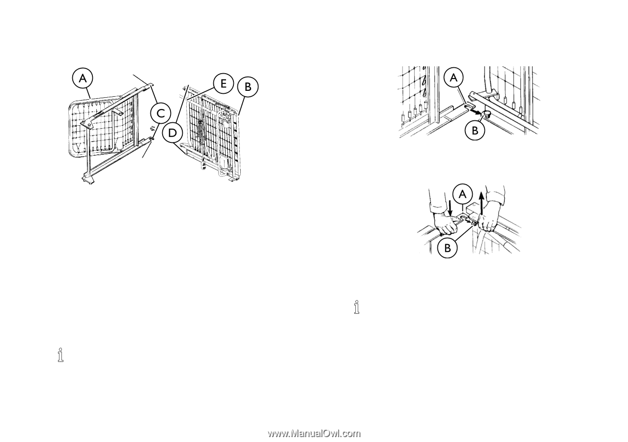
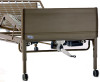
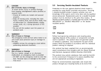
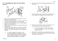
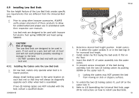
4.4 Assembling the Head and Foot Spring Sections Set-up 6. Place the head and foot springs approximately 90° from each other. 7. Hook the bottom head spring center mounting latch A to the bottom foot spring center mounting rivet B. 1. Remove the head spring section (5000 IVC) A of the bed from the packing carton. 2. Place the head spring section on its side to your left so the center mounting latches C are on the right. 3. Open the head spring section to a 45° to 90° angle to support the spring section. 4. Remove the foot spring section B of the bed from the packing carton. 5. Place the foot spring section on its side on your right with the head spring pull tube E at the top of the assembly. The center mounting rivets D should be on the left. For set-up purposes, the motors on the semi-electric (5890IVC and 5891IVC) and full electric (5490IVC and 5491IVC) foot springs as well as the crank handles on the manual foot springs (5770IVC) should be on your right. 1114836-H-05 8. Hook the top head spring center mounting latch A to the top foot spring center mounting rivet B. It may be necessary to lift the head spring or foot spring slightly to secure the mounting latches and rivets. 9. After head and foot springs are connected, push the springs into a horizontal (straight) position while keeping the springs on their sides. 21
-
 1
1 -
2
-
3
-
4
-
5
-
6
-
7
-
8
-
9
-
10
-
11
-
12
-
13
-
14
-
15
-
 16
16 -
 17
17 -
 18
18 -
 19
19 -
 20
20 -
 21
21 -
 22
22 -
 23
23 -
 24
24 -
 25
25 -
 26
26 -
27
-
28
-
29
-
30
-
31
-
32
-
33
-
34
-
35
-
36
-
37
-
38
-
39
-
40
-
41
-
42
-
43
-
44
-
45
-
46
-
47
-
48
 |
 |