Invacare LEO-3B Owners Manual - Page 42
Wheels and Casters
 |
View all Invacare LEO-3B manuals
Add to My Manuals
Save this manual to your list of manuals |
Page 42 highlights
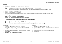
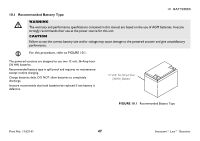
9 WHEELS AND CASTERS 9 Wheels and Casters ƽ WARNING After any adjustments, repair or service and before use, make sure that all attaching hardware is tightened securely otherwise injury or damage may result. Before performing any maintenance, adjustment or service, turn power Off and remove key from ignition. 9.1 Removing/Installing the Drive Wheels For this procedure, refer to FIGURE 9.1 on page 42. This procedure applies to the rear wheels of the four wheel and three wheel models. Removing 1. Turn power off and remove the key from the ignition. 2. Remove the seat. Refer to Removing/Installing the Seat on page 33. 3. Place the rear frame assembly (not shown) up on blocks so that the drive wheels are off the ground. 4. Remove the cap, locknut and small washer from the threaded end of the drive shaft. 5. Remove the existing drive wheel assembly from the drive shaft. Use a wheel puller if necessary to remove the wheel from the drive shaft. 6. Remove the large washer from the drive shaft. 7. Remove keystock from drive shaft. Set aside. 8. If necessary, repeat STEPS 1-7 to remove other drive wheel. Keystock Drive Wheel Drive Shaft Threaded End Large Washer Small Washer Locknut Cap FIGURE 9.1 Removing/Installing the Drive Wheels Invacare® Leo™ Scooter 42 Part No. 1163141
-
 1
1 -
2
-
3
-
4
-
5
-
6
-
7
-
8
-
9
-
10
-
11
-
12
-
13
-
14
-
15
-
16
-
17
-
18
-
19
-
20
-
21
-
22
-
23
-
24
-
25
-
26
-
27
-
28
-
29
-
30
-
31
-
32
-
33
-
34
-
35
-
36
-
 37
37 -
 38
38 -
 39
39 -
 40
40 -
 41
41 -
 42
42 -
 43
43 -
 44
44 -
 45
45 -
 46
46 -
 47
47 -
48
-
49
-
50
-
51
-
52
-
53
-
54
-
55
-
56
-
57
-
58
-
59
-
60
 |
 |
