Invacare LEO-3B Owners Manual - Page 48
Removing/Installing the Batteries, Removing, Installing
 |
View all Invacare LEO-3B manuals
Add to My Manuals
Save this manual to your list of manuals |
Page 48 highlights
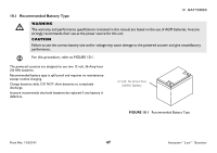
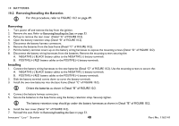
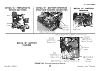
10 BATTERIES 10.2 Removing/Installing the Batteries For this procedure, refer to FIGURE 10.2 on page 49. Removing 1. Turn power off and remove the key from the ignition. 2. Remove the seat. Refer to Removing/Installing the Seat on page 33. 3. Pull up to remove the rear cover (Detail "A" of FIGURE 10.2). 4. Open the battery retention strap (Detail "B" of FIGURE 10.2). 5. Disconnect the battery harness connectors. 6. Remove the batteries from the base frame (Detail "C" of FIGURE 10.2). 7. Pull the battery terminal covers up on the battery wiring harnesses to expose the mounting screws (Detail "D" of FIGURE 10.2). 8. Disconnect the battery wiring harnesses from the batteries. Remove the mounting screws securing the: A. NEGATIVE (-) BLACK battery cables to the NEGATIVE (-) battery terminals. B. POSITIVE (+) RED battery cables to the POSITIVE (+) battery terminals. Installing 1. Connect the battery wiring harnesses to the new batteries (Detail "D" of FIGURE 10.2). Use the mounting screws to secure the: A. NEGATIVE (-) BLACK battery cables to the NEGATIVE (-) battery terminals. B. POSITIVE (+) RED battery cables to the POSITIVE (+) battery terminals. 2. Slide the battery terminal covers down to cover the battery terminals. 3. Install the two new batteries into the base frame (Detail "C" of FIGURE 10.2). Orient the batteries as shown in Detail "B" of FIGURE 10.2. 4. Connect the battery harness connectors. 5. Secure the batteries to the base frame using the battery retention strap. Securely tighten. The battery retention strap should go under the battery harnesses as shown in Detail "B" of FIGURE 10.2. 6. Install the rear cover (Detail "A" of FIGURE 10.2). 7. Reinstall the seat. Refer to Removing/Installing the Seat on page 33. Invacare® Leo™ Scooter 48 Part No. 1163141
-
 1
1 -
2
-
3
-
4
-
5
-
6
-
7
-
8
-
9
-
10
-
11
-
12
-
13
-
14
-
15
-
16
-
17
-
18
-
19
-
20
-
21
-
22
-
23
-
24
-
25
-
26
-
27
-
28
-
29
-
30
-
31
-
32
-
33
-
34
-
35
-
36
-
37
-
38
-
39
-
40
-
41
-
42
-
 43
43 -
 44
44 -
 45
45 -
 46
46 -
 47
47 -
 48
48 -
 49
49 -
 50
50 -
 51
51 -
 52
52 -
 53
53 -
54
-
55
-
56
-
57
-
58
-
59
-
60
 |
 |
