Invacare V20RLR Owners Manual - Page 41
Adjusting Wheel Locks
 |
View all Invacare V20RLR manuals
Add to My Manuals
Save this manual to your list of manuals |
Page 41 highlights
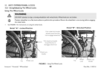
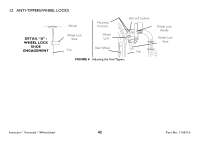
12 ANTI-TIPPERS/WHEEL LOCKS Adjusting Wheel Locks ƽ WARNING After any adjustments, repair or service and before use, make sure all attaching hardware is tightened securely. Otherwise injury or damage may occur. DO NOT attempt to stop a moving wheelchair with the wheel locks. WHEEL LOCKS ARE NOT BRAKES. 1. Ensure the wheel lock is in the open (unlocked position). 2. Loosen the bolt and locknut that secure the wheel lock assembly to the wheelchair frame. 3. Reposition the wheel lock so that when engaged, the wheel lock shoe embeds the tire 1/8-inch and holds the wheelchair. 4. Securely tighten the bolt and locknut securing the wheel lock to the wheelchair frame. 5. Engage the wheel lock. 6. Measure the distance the wheel lock is embedded into the tire as shown in detail "A" of FIGURE 4. Any wheel lock adjustment should embed the wheel lock shoe at least 1/8-inch into the tire when engaged. 7. Repeat the STEPS 1-6 until the wheel lock shoe embeds the tire 1/8-inch and holds the wheelchair. 8. Repeat STEPS 1-7 for the opposite wheel lock. 9. If the measurement of 1/8-inch cannot be achieved, remove the bolt and locknut that secure the wheel lock to the wheelchair frame and mount the wheel lock in one of two mounting positions. 10. Repeat STEPS 1-9 until the wheel lock holds the wheelchair. If the correct measurement still cannot be achieved, contact a qualified technician. Part No. 1148116 41 Invacare® Veranda™Wheelchair
-
 1
1 -
2
-
3
-
4
-
5
-
6
-
7
-
8
-
9
-
10
-
11
-
12
-
13
-
14
-
15
-
16
-
17
-
18
-
19
-
20
-
21
-
22
-
23
-
24
-
25
-
26
-
27
-
28
-
29
-
30
-
31
-
32
-
33
-
34
-
35
-
 36
36 -
 37
37 -
 38
38 -
 39
39 -
 40
40 -
 41
41 -
 42
42 -
 43
43 -
 44
44
 |
 |