JVC FS-G5 Instruction Manual - Page 8
Hook Up
 |
View all JVC FS-G5 manuals
Add to My Manuals
Save this manual to your list of manuals |
Page 8 highlights
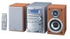
Step 3: Hook Up If you need more detailed information, see page 6. Illustrations of the input/output terminals below are typical examples. When you connect other components, refer also to their manuals since the terminal names actually printed on the rear may vary. Turn the power off to all components before connections. For better FM/AM reception Outdoor FM antenna (not supplied) AM loop antenna Keep it connected. White AM ANTENNA LOAMOP EXT GND Vynile-covered wire (not supplied) Extend it horizontally. Disconnect the supplied FM antenna, and connect to an outdoor FM antenna using a 75 Ω wire with coaxial type connector. To a wall outlet Plug the AC power cord only after all connections are complete. 4
-
 1
1 -
2
-
 3
3 -
 4
4 -
 5
5 -
 6
6 -
 7
7 -
 8
8 -
 9
9 -
 10
10 -
 11
11 -
 12
12 -
 13
13 -
14
-
15
-
16
-
17
-
18
-
19
-
20
-
21
-
22
-
23
-
24
-
25
-
26
-
27
-
28
-
29
 |
 |

4
Step
3
: Hook Up
If you need more detailed information, see page 6.
AM
EXT
GND
AM
EXT
GND
AM
LOOP
ANTENNA
Illustrations of the input/output terminals below are typical
examples.
When you connect other components, refer also to their
manuals since the terminal names actually printed on the rear
may vary.
Turn the power off to all components before connections.
To a wall outlet
Plug the AC power cord only after all connections are complete.
Disconnect the supplied FM antenna, and connect to an outdoor FM
antenna using a 75
Ω
wire with coaxial type connector.
Vynile-covered wire (not supplied)
Extend it horizontally.
AM loop antenna
Keep it connected.
For better FM/AM reception
Outdoor FM
antenna
(not supplied)
White