Kenwood KAC-746 User Manual - Page 4
Controls, a large variety of systems by combining the switches and functions described
 |
View all Kenwood KAC-746 manuals
Add to My Manuals
Save this manual to your list of manuals |
Page 4 highlights
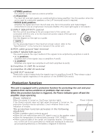
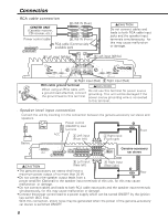
Controls This is a 4 channel amplifier including 2 stereo amplifiers in a body. One amplifier is referred to as amplifier A and the other is amplifier B. This unit is compatible with a large variety of systems by combining the switches and functions described in the following. 1 5 FUSE(30A) POWER IN GND BATT P.CON(REMOTE) SPEAKER OUTPUT BRIDGED A A B L RB BRIDGED LEFT RIGHT SPEAKER LEVEL INPUT LEFT RIGHT A SPEAKER LEVEL INPUT A B B L R 234 6 7 8 9 0 ! @ GND 100 80 100 150 INPUT SENSITIVITY(V) 0.5 0.3 80 FILTER OPERATION 150 OFF 1.0 HPF LPF 50 LPF 200 50 HPF 200 MIN MAX FREQUENCY(Hz) STEREO MONO(Lch) L + R AB MONO L R A CONTROL A INPUT SELECTOR A LINE IN B A+B LINE OUT INPUT L SENSITIVITY(V) 0.5 0.3 100 80 150 100 OPERATION FILTER 80 1.0 OFF 150 HPF LPF MIN R MAX STEREO MONO(Lch) L + R 50 LPF 200 50 HPF 200 FREQUENCY(Hz) CONTROL B 4 CHANNEL POWER AMPLIFIER Amplifier A # $ % ^ Amplifier B 1 Fuse (30 A) 2 Battery terminal 3 Ground terminal 4 Power control (REMOTE) terminal 5 Amplifier A speaker output terminals 6 Amplifier B speaker output terminals 7 Speaker level input terminals 8 FREQUENCY control When the FILTER switch is set to the HPF (High-Pass Filter) or LPF (Low-Pass Filter) position, the threshold frequency can be adjusted with this control. 9 FILTER switch High-pass or low-pass filtering can be applied to the speaker output according to the setting of this switch. 0 OPERATION switch The amplification methods of the signals input to amplifiers A and B can be selected independently according to the setting of this switch. 4
-
 1
1 -
 2
2 -
 3
3 -
 4
4 -
 5
5 -
 6
6 -
 7
7 -
 8
8 -
 9
9
 |
 |
