Kenwood TS-590S User Manual - Page 60
Beep Function
 |
View all Kenwood TS-590S manuals
Add to My Manuals
Save this manual to your list of manuals |
Page 60 highlights
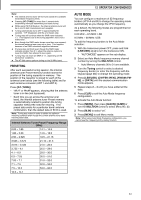
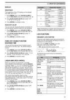
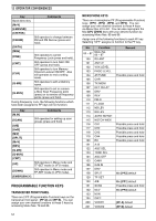
12 OPERATOR CONVENIENCES The table below is an example of setting the Auto Mode frequency. Channel No. Frequency (MHz) Mode Operation Range (MHz) 00 1.620 AM 0.030 ≤ f < 1.620 01 2.000 CW 1.620 ≤ f < 2.000 02 3.500 LSB 2.000 ≤ f < 3.500 03 3.525 CW 3.500 ≤ f < 3.525 04 10.100 LSB 3.525 ≤ f < 10.100 05 10.150 CW 10.100 ≤ f < 10.150 06 14.000 USB 10.150 ≤ f < 14.000 07 14.070 CW-R 14.000 ≤ f < 14.070 08 14.112 FSK 14.070 ≤ f < 14.112 09 18.068 USB 14.112 ≤ f < 18.068 10 18.110 CW 18.068 ≤ f < 18.110 11 21.000 USB 18.110 ≤ f < 21.000 12 21.070 CW 21.000 ≤ f < 21.070 13 21.125 FSK-R 21.070 ≤ f < 21.125 14 21.150 CW 21.125 ≤ f < 21.150 15 24.890 USB 21.150 ≤ f < 24.890 16 24.930 CW 24.890 ≤ f < 24.930 17 28.000 USB 24.930 ≤ f < 28.000 18 28.070 CW 28.000 ≤ f < 28.070 19 28.150 FSK 28.070 ≤ f < 28.150 20 28.200 CW 28.150 ≤ f < 28.200 21 29.000 USB 28.200 ≤ f < 29.000 22 30.000 FM-DATA 29.000 ≤ f < 30.000 23 50.000 USB 30.000 ≤ f < 50.000 24 50.100 CW 50.000 ≤ f < 50.100 25 51.000 USB 50.100 ≤ f < 51.000 26 52.000 FM 51.000 ≤ f < 52.000 27 52.000 LSB 28 52.000 LSB 29 52.000 LSB 30 52.000 LSB 31 52.000 LSB • The frequencies for channels 27 ~ 31 have not been configured, but because they are the same frequency as channel 26, they will be FM mode 51.0 MHz ≤ f < 52.0 MHz. • Since the frequencies above 52.0 MHz have not been configured, they will be USB mode 52.0 MHz ≤ f < 60.0 MHz 52 BEEP FUNCTION The Beep function provides you confirmation of entry, error status, and malfunctions of the transceiver. Although you can turn the beep function OFF by accessing Menu No. 03, we recommend you leave it ON in order to detect unexpected errors and malfunctions. You can also change the output level of the beeps by accessing Menu No. 03 and selecting "1" to "9". The transceiver generates the following Morse code to tell you which mode is selected when you change operating modes: Mode Morse Code Output USB LSB • • - (U) (L) CW - • - • (C) FSK • - • (R) AM • - (A) FM (F) USB-DATA LSB-DATA (UD) (LD) CW-R (CR) FSK-R FM-NAR FM-DATA (RR) (FN) (FD) FM-NAR-DATA FND) The transceiver also generates the following warning, confirmation, and malfunction beeps. Beep Type Meaning Short, high pitch A valid key is pressed. Double, high pitch A secondary function is selected. 3 times, high pitch The third function is accepted. Long, high pitch A key entry is accepted, Scan starts, or AT tune has completed. Short, regular A function is turned OFF. Short, low pitch An invalid key is pressed. Morse "UL" The internal PLL circuit unlock status is detected. Morse "S" CW Auto Tune cannot complete, or an invalid frequency is entered. Morse "5" AT Tune cannot be completed within the specified time. Morse "SWR" The antenna's SWR is too high (over 10:1) to perform AT tune. Morse "CHECK" 1 minute before the APO (Auto Power Off) function switches the transceiver OFF, a protection circuit is ON. or an invalid voltage is detected. Morse "BT" Waiting for a CW message to be recorded. Morse "AR" The current message memory is full.
-
 1
1 -
2
-
3
-
4
-
5
-
6
-
7
-
8
-
9
-
10
-
11
-
12
-
13
-
14
-
15
-
16
-
17
-
18
-
19
-
20
-
21
-
22
-
23
-
24
-
25
-
26
-
27
-
28
-
29
-
30
-
31
-
32
-
33
-
34
-
35
-
36
-
37
-
38
-
39
-
40
-
41
-
42
-
43
-
44
-
45
-
46
-
47
-
48
-
49
-
50
-
51
-
52
-
53
-
54
-
 55
55 -
 56
56 -
 57
57 -
 58
58 -
 59
59 -
 60
60 -
 61
61 -
 62
62 -
 63
63 -
 64
64 -
 65
65 -
66
-
67
-
68
-
69
-
70
-
71
-
72
-
73
-
74
-
75
-
76
-
77
-
78
-
79
-
80
-
81
-
82
-
83
-
84
-
85
-
86
-
87
-
88
-
89
-
90
-
91
-
92
 |
 |
