Kenwood VR-5900 User Manual 1
Kenwood VR-5900 Manual
 |
View all Kenwood VR-5900 manuals
Add to My Manuals
Save this manual to your list of manuals |
Kenwood VR-5900 manual content summary:
- Kenwood VR-5900 | User Manual 1 - Page 1
Connection and Setup Guide Digital Audio/V How To Connect And Set Up Your VR-5900 i ideo Receiver B60-4883-10 02 CH (K,P) OC 0011 - Kenwood VR-5900 | User Manual 1 - Page 2
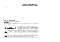
VR-5900 is designed for operation as follows. U.S.A. and Canada AC 120 V only Before Applying Power Read this section AN EQUILATERAL TRIANGLE IS INTENDED TO ALERT THE USER TO THE PRESENCE OF IMPORTANT OPERATING AND MAINTENANCE (SERVICING) INSTRUCTIONS IN THE LITERATURE ACCOMPANYING THE APPLIANCE. - Kenwood VR-5900 | User Manual 1 - Page 3
Audio-Video Receiver Welcome to the Connection and Setup Guide for your new Kenwood audio-video receiver. The VR-5900 offers 3 kinds of 5.1-channel digital surround sound decoding: • Dolby Digital, for the hundreds of currently available Dolby Digital DVDs and LaserDiscs. • DTS, a well-established - Kenwood VR-5900 | User Manual 1 - Page 4
: 669114. Other patents pending. The above are additional trademarked names appearing in this manual. All other products named are trademarks of their respective companies. As an ENERGY STAR® Partner, Kenwood Corporation has deter- mined that this products meets the ENERGY STAR® guidelines for - Kenwood VR-5900 | User Manual 1 - Page 5
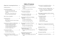
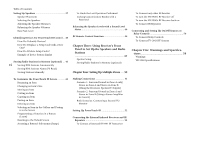
an Amplifier 8 Connecting Your TV 10 To Connect a TV What if I Want to Watch TV without Turning on the Receiver? Table of Contents To Connect a Kenwood 200-Disc CD Changer To Connect Any Other Primary CD Player or Changer To Connect a Secondary CD Player Connecting Your DVD Player 18 To Connect - Kenwood VR-5900 | User Manual 1 - Page 6
Storing RDS Stations Name (PS Read) Storing Stations Manually To Undo the Last Operation Performed Locking Customization Results To Connect any other IR Receiver To turn the VR-5900's RF Receiver off To turn the VR-5900's RF Receiver back on To Connect IR Repeaters a Kenwood IR-9991 IR Transceiver - Kenwood VR-5900 | User Manual 1 - Page 7
the Kenwood VR-5900 Connection and Setup Guide. This chapter guides you through connecting your home entertainment devices to your new Kenwood audiovideo can cause your new receiver to malfunction. Before You Begin This manual covers the most common and standard connections to the receiver. - Kenwood VR-5900 | User Manual 1 - Page 8
connectors * The RS-232C connector is provided for future capability (to connect a commercially marketed controller having the capability of controlling the VR-5900). ** Note that the digital input jacks are linked to specific audio and video component jacks. Make sure that each source device is - Kenwood VR-5900 | User Manual 1 - Page 9
Chapter One : Connecting Your Devices Noting Your Devices Jack Set Device Manufacturer PHONO CD1 MD/TAPE1 CD2/TAPE2 MONITOR CD-R MONITOR OUT (TV on PowerTouch III) VIDEO1 VIDEO2 VIDEO3 VIDEO4 DVD Use this table and the diagram on the preceding page to plan your connections before you - Kenwood VR-5900 | User Manual 1 - Page 10
Connections Chapter One : Connecting Your Devices R FRONT Connecting Your Speakers R SURROUND L SURROUND CENTER L FRONT IR RECEIVER IN IR REPEATER OUT/ IR RECEIVER IR OUT RELAY TV ON/OFF SL16 TEXT SYSTEM DVD CONTROL IN LCD CONTROL SENSOR CONTROL RF REMOTE ANTENNA 4 VIDEO R L SUB - Kenwood VR-5900 | User Manual 1 - Page 11
Connections Chapter One : Connecting Your Devices Connecting Your Speakers, continued Do not plug in the receiver to AC power until all connections have been made. To Connect Front Speakers Only: If you only intend to listen to stereo sound (as opposed to surround sound), you may simply connect a - Kenwood VR-5900 | User Manual 1 - Page 12
Connections Chapter One : Connecting Your Devices POWERED SUBWOOFER Connecting Your Speakers, continued R SURROUND BACK L SURROUND BACK Power Amp. 6 IR RECEIVER IN IR REPEATER OUT/ IR RECEIVER IR OUT RELAY TV ON/OFF SL16 TEXT SYSTEM DVD CONTROL IN LCD CONTROL SENSOR CONTROL RF REMOTE - Kenwood VR-5900 | User Manual 1 - Page 13
OUT jacks to the 2- channel power amplifiers' input jacks as shown to the left. 7 2. Connect the speakers to the power amplifier according to the amplifiers' instruction manuals. - Kenwood VR-5900 | User Manual 1 - Page 14
Connections Chapter One : Connecting Your Devices What if I Have an Amplifier? R FRONT Power Amp. CENTER Power Amp. L FRONT IR RECEIVER IN IR REPEATER OUT/ IR RECEIVER IR OUT RELAY TV ON/OFF SL16 TEXT SYSTEM DVD CONTROL IN LCD CONTROL SENSOR CONTROL RF REMOTE ANTENNA 8 VIDEO R L SUB - Kenwood VR-5900 | User Manual 1 - Page 15
receiver's PRE OUT jacks to the amplifiers' input jacks as shown to the left. 2. Connect the speakers to the power amplifiers according to the amplifiers' instruction manuals. 9 - Kenwood VR-5900 | User Manual 1 - Page 16
Connections Chapter One : Connecting Your Devices Connecting Your TV 10 COMPONENT VIDEO IN IR RECEIVER IN IR REPEATER OUT/ IR RECEIVER IR OUT RELAY TV ON/OFF SL16 TEXT SYSTEM DVD CONTROL IN LCD CONTROL SENSOR CONTROL VIDEO R L SUB WOOFER CENTER ZONE B PRE OUT DIGITAL OUT COMPONENT - Kenwood VR-5900 | User Manual 1 - Page 17
to the VR-5900. Please refer to your TV's instructions for more detail about its connection jacks and capabilities. The instructions in this connections. Connect the receiver to the TV according to the RF modulator's instruction manual. 4. Go to "Noting Your Devices" on page 3 and note which - Kenwood VR-5900 | User Manual 1 - Page 18
Connections Chapter One : Connecting Your Devices Connecting Your Cable TV or Satellite Tuner 12 COMPONENT VIDEO OUT IR RECEIVER IN IR REPEATER OUT/ IR RECEIVER IR OUT RELAY TV ON/OFF SL16 TEXT SYSTEM DVD CONTROL IN LCD CONTROL SENSOR CONTROL DIGITAL OUTOPTICAL or COAXIAL Remove protective - Kenwood VR-5900 | User Manual 1 - Page 19
to the VR-5900. Please refer to your tuner's instructions for more detail about its connection jacks and capabilities. The instructions in this one for coaxial connection and one for optical connection. Your Satellite tuner supports one or the other of these connection methods-do not connect both. - Kenwood VR-5900 | User Manual 1 - Page 20
Connections Chapter One : Connecting Your Devices Connecting Your VCR(s) 14 S-VIDEO IN S-VIDEO OUT IR RECEIVER IN IR REPEATER OUT/ IR RECEIVER IR OUT RELAY TV ON/OFF SL16 TEXT SYSTEM DVD CONTROL IN LCD CONTROL SENSOR CONTROL VIDEO R L SUB WOOFER CENTER ZONE B PRE OUT DIGITAL OUT - Kenwood VR-5900 | User Manual 1 - Page 21
connected all your devices. This section focuses on the connections from your VCR to the VR-5900. Please refer to your VCR's instructions for more detail about its connection jacks and capabilities. The instructions in this section show one of several possible variations on connecting your VCR. For - Kenwood VR-5900 | User Manual 1 - Page 22
DC5V 10mA A FM 75Ω AM GND ANTENNA RF REMOTE ANTENNA CENTER SPEAKER (6-16Ω) C R SURROUND SPEAKERS (6-16Ω) L A FRONT SPEAKERS B (6-16Ω) OUTPUT A (CD1) OUTPUT B (CD2)* COMMUNICATION CABLE - KENWOOD ONLY SYSTEM CONTROL CABLE - KENWOOD ONLY *KENWOOD CD-3280M or CD-2280M ONLY - Kenwood VR-5900 | User Manual 1 - Page 23
the VR-5900. Please refer to your changer's instructions for more detail about its connection jacks and capabilities. Each set of instructions in . Your CD player supports one or the other of these connection methods-do not connect both. 3. If you are connecting a Kenwood CD Player with system - Kenwood VR-5900 | User Manual 1 - Page 24
Connections Chapter One : Connecting Your Devices Connecting Your DVD Player 18 3 8 7 4¢ DIGITAL OUT - OPTICAL or COAXIAL IR RECEIVER IN IR REPEATER OUT/ IR RECEIVER IR OUT RELAY TV ON/OFF SL16 TEXT SYSTEM DVD CONTROL IN LCD CONTROL SENSOR CONTROL Remove protective cap before connecting. - Kenwood VR-5900 | User Manual 1 - Page 25
VR-5900. Please refer to your DVD player's instructions for more detail about its connection jacks and capabilities. The instructions connections, one for coaxial connection and one for optical connection. Your DVD player supports one or the other of these connection methods-do not connect both. 5. - Kenwood VR-5900 | User Manual 1 - Page 26
Connections Chapter One : Connecting Your Devices Connecting Your CD-R Recorder 20 DIGITAL RECORD IN - OPTICAL or COAXIAL Remove protective cap before connecting. VIDEO R L SUB WOOFER CENTER ZONE B PRE OUT DIGITAL OUT COMPONENT VIDEO Y R SURROUND BACK L R SURROUND L R FRONT L PRE OUT - Kenwood VR-5900 | User Manual 1 - Page 27
VR-5900. Please refer to your CD-R recorder instructions for more detail about its connection jacks and capabilities. Each set of instructions one for coaxial connection and one for optical connection. Your CD-R recorder supports one or the other of these connection methods-do not connect both. - Kenwood VR-5900 | User Manual 1 - Page 28
REMOTE ANTENNA CENTER SPEAKER (6-16Ω) C R SURROUND SPEAKERS (6-16Ω) L A FRONT SPEAKERS B (6-16Ω) DIGITAL OUT - OPTICAL or COAXIAL RECORD IN (ANALOG) PLAY OUT (ANALOG) SYSTEM CONTROL CABLE - KENWOOD ONLY - Kenwood VR-5900 | User Manual 1 - Page 29
VR-5900. Please refer to your MD recorder or tape deck's instructions for more detail about its connection jacks and capabilities. Each set of instructions optical connection. Your MD recorder supports one or the other of 3. If you are connecting a Kenwood tape deck with system control, connect - Kenwood VR-5900 | User Manual 1 - Page 30
Connections Chapter One : Connecting Your Devices Connecting Your Secondary CD Player or Tape Deck 24 IR RECEIVER IN IR REPEATER OUT/ IR RECEIVER IR OUT RELAY TV ON/OFF SL16 TEXT SYSTEM DVD CONTROL IN LCD CONTROL SENSOR CONTROL VIDEO R L SUB WOOFER CENTER ZONE B PRE OUT DIGITAL OUT - Kenwood VR-5900 | User Manual 1 - Page 31
VR-5900. Please refer to your CD player or tape deck's instructions for more detail about its connection jacks and capabilities. Each set of instructions not connect the system control cable from the second tape deck, even if it supports system control. 3. Go to "Noting Your Devices" on page 3 and - Kenwood VR-5900 | User Manual 1 - Page 32
Connections Chapter One : Connecting Your Devices Connecting Your Laser Disc Player (with AC-3 RF Output) 26 AC-3 DIGITAL RF OUT OUT OPTICAL or COAXIAL Remove protective cap before inserting DIGITAL OUTPUT RF INPUT COAX. AC-3 RF DIGITAL INPUT COAX. OPT. DC IN RF DEMODULATOR DIGITAL OUT - Kenwood VR-5900 | User Manual 1 - Page 33
all your devices. You must purchase an RF Demodulator (such as the Kenwood DEM-9991D available from one of our parts distributors) if you plan to a player with a Dolby Digital (AC-3) RF output with this receiver. These instructions describe how to connect a laser disc player with an AC-3 RF output. - Kenwood VR-5900 | User Manual 1 - Page 34
Connections Chapter One : Connecting Your Devices Connecting Your Laser Disc Player (without AC-3 RF Output) 28 DIGITAL OUT OPTICAL or COAXIAL IR RECEIVER IN IR REPEATER OUT/ IR RECEIVER IR OUT RELAY TV ON/OFF SL16 TEXT SYSTEM DVD CONTROL IN LCD CONTROL SENSOR CONTROL VIDEO R L SUB WOOFER - Kenwood VR-5900 | User Manual 1 - Page 35
the receiver to AC power until you have connected all your devices. These instructions describe how to connect a laser disc player with a PCM Digital output. jack on the receiver as shown to the left. Your laser disc player supports only one of the digital connection methods-do not connect both. 5. - Kenwood VR-5900 | User Manual 1 - Page 36
connected all your devices. This section focuses on the connections from your turntable/ record player to the VR-5900. Please refer to your turntable/ record player's instructions for more detail about its connection jacks and capabilities. To Connect a Turntable/Record Player: 1. Connect the audio - Kenwood VR-5900 | User Manual 1 - Page 37
focuses on the connections from your camcorder or VCR to the front of the VR-5900. Please refer to your camcorder or VCR's instructions for more detail about its connection jacks and capabilities. These instructions describe how to connect a camcorder or VCR quickly and probably temporarily to the - Kenwood VR-5900 | User Manual 1 - Page 38
these devices in a set of chained connections. Do not connect system control cables to any device not specified by Kenwood. Using a system control cable with a device that does not support them can damage the device. Make sure system control plugs are firmly seated in the appropriate jacks. System - Kenwood VR-5900 | User Manual 1 - Page 39
Antenna RF REMOTE ANTENNA The PowerTouch III controller for the VR-5900 communicates with the receiver via RF transmission. To properly provides the best reception. FM Outdoor Antenna FM 75Ω AM GND ANTENNA Kenwood recommends a permanently installed outdoor FM antenna for best FM reception. To - Kenwood VR-5900 | User Manual 1 - Page 40
range (see "How is PowerTouch III Powered?" on page 5 of the Users' Guide) PowerTouch III's display may show incorrect information. When your batteries begin to run competent custom installer. For more information, call 1-800-KENWOOD or visit the Kenwood Web site at http://www.kenwoodusa.com. If you - Kenwood VR-5900 | User Manual 1 - Page 41
do not need to do this unless you experience a problem. 1. Open the cover. 2. Use the stylus to condition, please follow the instructions on page 104 of the Users' Guide. After "Calibrating the Touch is not ON, etc., the model type can be selected manually. In this case, select the "Model 1" in step - Kenwood VR-5900 | User Manual 1 - Page 42
to copy all the settings stored in your PowerTouch III to a second PowerTouch III. Instructions are included in a separately sold PowerTouch III package. (Only for some areas) • Macro (See the VR-5900 Users' Guide) This menu setting allows you to create custom macros that perform several operations - Kenwood VR-5900 | User Manual 1 - Page 43
ft (1 meter) above the ears of the listeners. Selecting the Speakers 1. Touch on the Setup Surround menu to open the Speaker Selection menu. 2. Kenwood provides two ways to set up your speakers: Quick Setup: Use this method for a simplified setup where you identify whether a speaker is present - Kenwood VR-5900 | User Manual 1 - Page 44
Remote Setup Chapter Two : Setting Up PowerTouch III Custom setup: Use this method for a more customized setup where you determine more of the speaker settings, such as the bandwidth of the sound sent to each speaker. Custom setup configures the following: SW=subwoofer, L=front left, R=front right - Kenwood VR-5900 | User Manual 1 - Page 45
of Dolby Digital and DTS programs can contain up to 10dB more energy than the other channels, which is enough to damage some speakers. The VR-5900 has a bass limiter circuit that keeps the output to your subwoofer (or left & right speakers, if your system doesn't have a subwoofer) within safe limits - Kenwood VR-5900 | User Manual 1 - Page 46
Kenwood devices are connected with a system control cable, be sure to select the code preceded by "Sys-" or "System". This instructs ?" on page 35 of the Users' Guide and note which icon corresponds to which connected appropriate section of Chapter One of this manual. 2. Follow the steps under "How - Kenwood VR-5900 | User Manual 1 - Page 47
Two : Setting Up PowerTouch III Storing Radio Stations in Memory (optional) Your new PowerTouch III provides two ways to store radio stations: • Manual Memory, which allows you to enter and store specific stations. • RDS Automatic Memory, which searches for stations broadcasting an RDS signal and - Kenwood VR-5900 | User Manual 1 - Page 48
controls: on the HOME1 menu to access the Tuner 3. Touch to choose the receiving band. 4. Touch to switch between Auto tuning and Manual tuning. Select Manual if you experience interference due to weak radio signals. 5. Choose the station you want to store using one of the following methods - Kenwood VR-5900 | User Manual 1 - Page 49
BS (backspace) button and enter a new name. The button displays other characters. For details on the keyboard operation, see page 8 of the User's Guide. 4. Touch the button to enter the name. 43 5. To continue customization, touch another item then pro- ceed to the next operation. Touch the - Kenwood VR-5900 | User Manual 1 - Page 50
Chapter Two : Setting Up PowerTouch III Remote Setup Moving an Item 1. Go to the screen you want to customize and touch the icon. (Customization cannot be performed on screens where the icon is grayed out.) 2. When the customization icons are displayed, touch the icon so that it is highlighted ( - Kenwood VR-5900 | User Manual 1 - Page 51
Chapter Two : Setting Up PowerTouch III Remote Setup 4 inches (10 cm) BACKLIGHT • "Complete" is displayed when learning completes successfully. • "Error" is displayed when learning fails. Be sure to use the device's original remote. PowerTouch III will not learn commands from other universal - Kenwood VR-5900 | User Manual 1 - Page 52
III Balancing the Speaker Levels with a Sound Level Meter Note: These instructions assume you are using a Radio Shack SPL meter, model 33-2050. film soundtracks at the volumes intended by their makers when you set the VR-5900's volume control to 0dB. You can, of course, set the volume level - Kenwood VR-5900 | User Manual 1 - Page 53
Chapter Three : Using Receiver's Front Panel to Set Up the Speakers and Radio Stations Chapter Three: Using Receiver's Front Panel to Set Up the Speakers and Radio Stations Receiver Setup You can also perform the Speaker Setup and program preset radio stations using the receiver's front panel. (If - Kenwood VR-5900 | User Manual 1 - Page 54
of Dolby Digital and DTS programs can contain up to 10dB more energy than the other channels, which is enough to damage some speakers. The VR-5900 has a bass limiter circuit that keeps the output to your subwoofer (or left & right speakers, if your system doesn't have a subwoofer) within safe limits - Kenwood VR-5900 | User Manual 1 - Page 55
‹) button to select the Tuner input. 2. Press the BAND button to choose the receiving band. 3. Press the AUTO button to select AUTO TUNING or MANUAL TUNING. 4. Press the MULTI CONTROL (fi/%) button to tune the station you want to store. 5. Press the MEMORY button. 6. Press the P.CALL (fi/%) button to - Kenwood VR-5900 | User Manual 1 - Page 56
Chapter Four: Setting Up Multiple Zones Chapter Four: Setting Up Multiple Zones The VR-5900 offers dual-zone output and control, which enables you to use a single receiver to control devices and speakers for two zones (rooms). Due to its - Kenwood VR-5900 | User Manual 1 - Page 57
This section describes how to connect speakers in the two zones to support the different scenarios. Before you read this section, Kenwood recommends reading "Connecting Making Connections Your Speakers" on page 4 of this manual. In addition, this section discusses how to connect a second TV/Monitor - Kenwood VR-5900 | User Manual 1 - Page 58
equipment from two different zones using your Kenwood PowerTouch III. To do so: 1. Devices For PowerTouch III Control" on page 40 of this manual. 2. Touch the (SETUP) on the Quick Access menu of the Users' Guide. 52 3. Touch to access multi-zone commands: If you plan on using the VR-5900 in a Dual - Kenwood VR-5900 | User Manual 1 - Page 59
Chapter Four: Setting Up Multiple Zones 53 Multiple Zones - Kenwood VR-5900 | User Manual 1 - Page 60
Chapter Four: Setting Up Multiple Zones Connecting the External Infrared Receivers and IR Repeaters IR RECEIVER IR-9991 AC ADAPTOR IR RECEIVER IR-9991 MONITOR IR OUT IR IN MONITOR IR IN IR OUT AC ADAPTOR Multiple Zones 54 IR RECEIVER IN IR REPEATER OUT/ IR RECEIVER IR OUT RELAY TV ON/OFF - Kenwood VR-5900 | User Manual 1 - Page 61
to the VR-5900 and use PowerTouch III's IR communication instead of RF. Kenwood's optional IR-9991 IR transceiver supports PowerTouch III repeaters: 1. Connect the IR repeater to the device as described in the repeater's manual. 2. Connect the IR repeater cable(s) to the Receiver's IR RE- PEATER OUT - Kenwood VR-5900 | User Manual 1 - Page 62
status Power On To Tip To Ring Switched between 0 V and 12 V by 0V a button on one of PowerTouch III's screens (see page 82 of the VR- 5900 Users' Guide). +12V 0V When the VR-5900's power is switched on. To Sleeve Ground Ground TV ON/OFF SENSOR - Kenwood VR-5900 | User Manual 1 - Page 63
or Relay Controls, continued The VR-5900 supports 2 types of additional external Guide) to accurately sense whether the TV is already on or off and adjust accordingly. To Connect Relay Controls: 1. Consult the relay control's manual for compatibility information and installation instructions - Kenwood VR-5900 | User Manual 1 - Page 64
modifications are expressly approved in the instruction manual. The user could lose the for help. FCC Compliance Notice Audio-video Receiver, VR-5900 This device comply with Part 15 of FCC Rules. interference that may cause undesired operation. KENWOOD U.S.A. CORPORATION 2201 East Dominguez St., - Kenwood VR-5900 | User Manual 1 - Page 65
(total 90 W, 0.75 A max.) Dimensions W : 440 mm (17-5/16") H : 191 mm (7-1/2") D : 416 mm (16-3/8") Weight (Net 19.9 kg (43.8 lb) Kenwood follows a policy of continuous advancements in development. For this reason, specifications may be changed without notice. Full performance may not be exhibited - Kenwood VR-5900 | User Manual 1 - Page 66
Index Numerics 200-Disc CD Changer connecting 17 connecting SL16 text cable 17 identifying to PowerTouch III 40 SL16/XS8 switch 17 A AM antenna connecting 33 preventing hum interference 33 amplifier connecting 6, 8 using in multiple zones 51 analog cables DVD player 19 laser disc - Kenwood VR-5900 | User Manual 1 - Page 67
CD-R recorder 20 S MD recorder 22 DVD player 18 LD player 26, 28 MD recorder 22 satellite tuner 12 S video cable cable TV 12 DVD player 18 laser disc player 26, 28 tape deck 22 system control chaining 32 T satellite tuner 12 tape deck P TV 10 connecting 22 powered subwoofer, - Kenwood VR-5900 | User Manual 1 - Page 68
For your records Record the serial number, found on the back of the unit, in the spaces designated on the warranty card, and the space provided below. Refer to the model and serial numbers whenever you call upon your dealer for information or service on this product. Model Serial Number
-
 1
1 -
 2
2 -
 3
3 -
 4
4 -
 5
5 -
 6
6 -
 7
7 -
8
-
9
-
10
-
11
-
12
-
13
-
14
-
15
-
16
-
17
-
18
-
19
-
20
-
21
-
22
-
23
-
24
-
25
-
26
-
27
-
28
-
29
-
30
-
31
-
32
-
33
-
34
-
35
-
36
-
37
-
38
-
39
-
40
-
41
-
42
-
43
-
44
-
45
-
46
-
47
-
48
-
49
-
50
-
51
-
52
-
53
-
54
-
55
-
56
-
57
-
58
-
59
-
60
-
61
-
62
-
63
-
64
-
65
-
66
-
67
-
68
 |
 |

i
Connection and Setup Guide
How To Connect And Set Up Your
VR-5900
r
e
v
i
e
c
e
R
o
e
d
i
V
/
o
i
d
u
A
l
a
t
i
g
i
D
B60-4883-10 02
CH
(K,P)
OC
0011