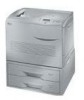
Kyocera FS 8000C FS-8000C Installation Instructions Rev-1
Kyocera FS 8000C - Color Laser Printer Manual
 |
View all Kyocera FS 8000C manuals
Add to My Manuals
Save this manual to your list of manuals |
Kyocera FS 8000C manual content summary:
- Kyocera FS 8000C | FS-8000C Installation Instructions Rev-1 - Page 1
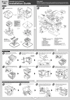
FS-8000C Series Printers Installation Guide Unpacking 1 Unpacking the Printer Yes! No! Warning: To avoid injury, the printer must be lifted and carried by two persons or more. Important! Installation should be performed only by a qualified service personnel. Kyocera Mita assumes no liability - Kyocera FS 8000C | FS-8000C Installation Instructions Rev-1 - Page 2
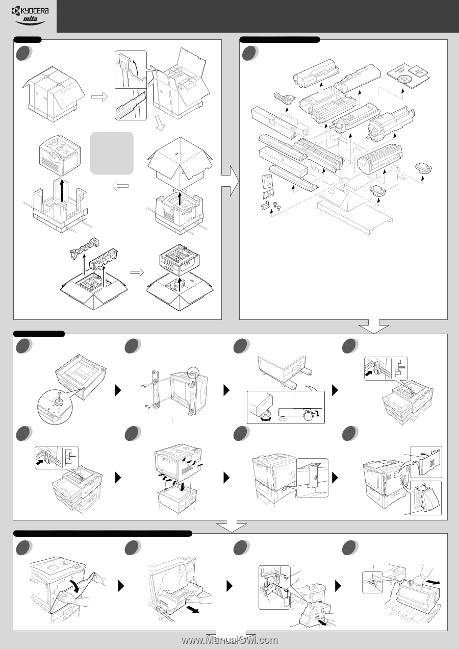
2001 by Kyocera Corporation. 14-9, Tamagawadai 2-Chome, Setagaya Ward, Tokyo 158-8610 Japan. All rights reserved. Installing the Fuser Unit, Oil Unit, Secondary Transfer Unit, and Waste Toner Bottle 15 16 Open the paper guide. Insert the fuser unit onto the paper feed unit. Fix the fuser unit
-
 1
1 -
 2
2
 |
 |
FS-8000C Series Printers
PF-30A for FS-8000C
PD-30 for FS-8000CD
Important!
Installation should be performed only by a qualified service personnel. Kyocera Mita
assumes no liability for any damage caused by an improper installation of the printer.
No!
Yes!
3
1
2
4
5
6
7
8
9
10
11
12
13
14
Placing the Printer
Checking Parts and Components
Unpacking
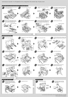
Using another topple-resistant bracket,
stack and joint the middle and top paper
feeder.
Place the printer over the paper feeders (by
at least two persons).
Join the printer and topmost paper feeder
with the jig provided by using one screw.
Using a topple-resistant bracket (supplied
with the CA-31B caster kit), stack and joint
the bottom and middle paper feeder.
Open the front cover.
Pull out thoroughly the paper feed unit.
Unscrew the screw. Remove the lock pin
and release the (green-colored) lock lever.
Pull out the primary transfer unit until it
stops.
While pushing the gray lever, pull out
the primary transfer unit. Make sure
not to scratch the roller.
Installation Guide
Continued on
the Reverse Page
Attaching the Caster kit (purchased
separately): Remove each one screw to
remove four feet.
Place the paper feeder in a proper location.
Lock the stopper for each caster. Turn the
bolts to adjust height.
Install the filter duct and the quick
reference guide holder. Peel the protective
tape off when attaching the holder.
Be sure to face
the longer end
towards the front
of the feeder.
Gray Lever
Filter Duct
Quick Reference
Guide Holder
Unpacking the Printer
Unpacking
the Paper Feeder
Warning: To
avoid injury, the
printer must be
lifted and
carried by two
persons or
more.
The following setup assumes three paper feeders to be installed with the printer (including the one supplied as a standard accessory), which requires a CA-31B caster kit to
be installed on the bottom of the bottom paper feeder. If the extra paper feeders are not installed, the CA-31 casters may be used. See the Operation Guide for more details.
1 Documents
Installation Guide (This sheet)
Quick Reference Guide
CD-ROM
2 Cyan Developer
3 Magenta Developer
4 Yellow Developer
5 Black Developer
6 Cyan Toner Container
7 Magenta Toner Container
8 Yellow Toner Container
1
2
3
4
5
6
7
8
9
10
11
12
13
13
14
15
16
17
18
9 Black Toner Container
10 Secondary Transfer Unit
11 Fuser Unit
12 Oil Unit
13 Waste Toner Bottles
14 Power Cord
15 Filter Duct
16 Quick Reference Guide Holder
17 Jig (Used in step 9)
18 Screws (Used in steps 9 and 16)
Lock Lever
Screw
Lock Pin
Stand the paper feeder on its back side.
Install the caster kit onto the bottom of the
paper feeder.
Installing the Fuser Unit, Oil Unit, Secondary Transfer Unit, and Waste Toner Bottle