Kyocera FS 8000C FS-8000C Installation Instructions Rev-1 - Page 2
by Kyocera Corporation. 14-9, Tamagawadai 2-Chome, Setagaya Ward, Tokyo 158-8610 Japan. All rights - black toner
 |
View all Kyocera FS 8000C manuals
Add to My Manuals
Save this manual to your list of manuals |
Page 2 highlights
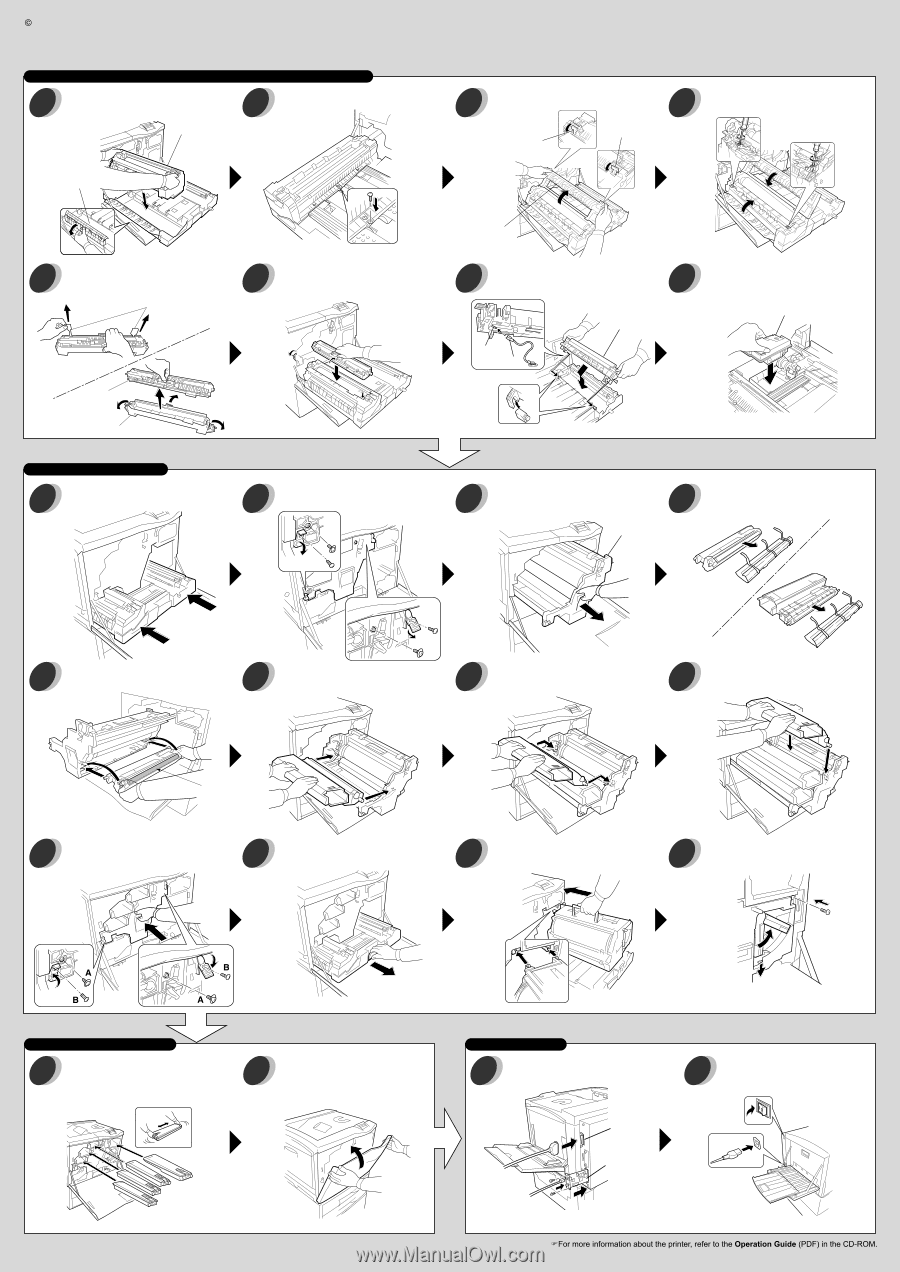
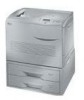
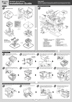
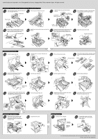
2001 by Kyocera Corporation. 14-9, Tamagawadai 2-Chome, Setagaya Ward, Tokyo 158-8610 Japan. All rights reserved. Installing the Fuser Unit, Oil Unit, Secondary Transfer Unit, and Waste Toner Bottle 15 16 Open the paper guide. Insert the fuser unit onto the paper feed unit. Fix the fuser unit with one screw. Fuser Unit Paper Guide Open the fuser top cover by the lock 17 buttons. 18 Firmly tighten two screws. Close the fuser top cover, then close the paper guide. Lock Button (green-colored) Lock Button (green-colored) Fuser Top Cover 19 Remove the oil sealing tapes from the oil unit. Unlatch three latches and then take out the oil unit from the cover. Oil Sealing Tapes 20 Install the oil unit onto the fuser unit until it is locked. 21 22 Connect the tab from the paper feed unit to the terminal of secondary transfer unit. Install the waste toner bottle. Then, install the secondary transfer unit. Secondary Transfer Unit Waste Toner Bottle Terminal Tab Oil Unit Cover Inserting the Developer Units 23 Close the paper feed unit. 24 Unscrew the four screws. Free the two stoppers. 25 Pull out the process frame. Peel off the tapes from the developer units 26 and remove the protective pad from each unit. Process Frame Black Cyan Magenta Yellow 27 Set the black developer facing the developing roller towards you. 28 Set the cyan developer. 29 Set the magenta developer. 30 Set the yellow developer. Developing Roller 31 32 Close the process frame and then close the stoppers. Fix the two (A) screws first, Pull out the paper feed unit. and then fix the two (B) screws. 33 Reinstall the primary transfer unit. Insert it thoroughly on the rails. 34 Close the lock lever. Fix the screw. Reinsert the paper feed unit. Installing the Toner Containers 35 Shake each toner container well before use. Install the four toner containers into their corresponding developer units. 36 Close the front cover. Black Yellow Magenta Cyan Making Connections 37 Connect to the computer. Parallel Interface Network Interface Card 38 Connect the power cord to the power outlet. Turn on the printer power switch. Printed in Japan 2001.08 EI 2BM80020C
-
 1
1 -
 2
2
 |
 |