LG 32LV3400 Owner's Manual - Page 27
LV2500, 32LV2520, LV3400, LV3500, LV3520, LV5300, LW5000, LW5300, LV355C, series, Stand Body,
 |
View all LG 32LV3400 manuals
Add to My Manuals
Save this manual to your list of manuals |
Page 27 highlights
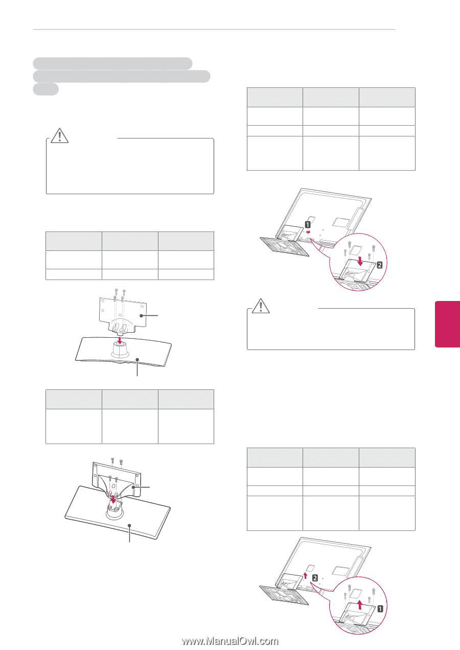
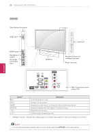
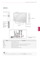
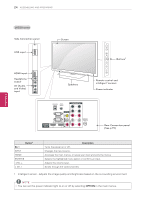
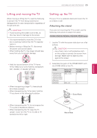
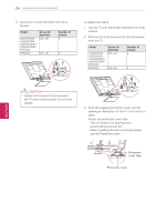
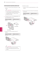
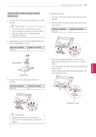
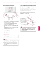
ASSEMBLING AND PREPARING 27 ENEGNLGISH 32LV2500, 32LV2520, LV3400, LV3500, LV3520, LV5300, LW5000, LW5300, LV355C series 1 Lay the TV with the screen side down on a flat surface. CAUTION yyLay a foam mat or soft protective cloth on the surface to protect the screen from damage. Make sure no objects press against the screen. 2 Assemble the parts of the STAND BODY with the STAND BASE of the TV. Model 32LV2500 32LV2520 LV5300 series Screw for assembly M4 x 14 M4 x 26 Number of screws 4 4 3 Secure the TV and the stand with the 4 screws. Model Screw for assembly 32LV2500 32LV2520 M4 x 14 LV5300 series M4 x 16 LV3400, LV3500, M4 x 12 LV3520, LW5000, LW5300, LV355C series Number of screws 4 4 4 Stand Body Stand Base Model Screw for assembly LV3400, LV3500, M4 x 12 LV3520, LW5000, LW5300, LV355C series Number of screws 4 Stand Body Stand Base CAUTION yyTighten the screws firmly to prevent the TV from tilting forward. Do not over tighten. To detach the stand, 1 Lay the TV with the screen side down on a flat surface. 2 Remove the 4 screws and pull the stand away from the TV. Model Screw for assembly 32LV2500 32LV2520 M4 x 14 LV5300 series M4 x 16 LV3400, LV3500, M4 x 12 LV3520, LW5000, LW5300, LV355C series Number of screws 4 4 4
-
 1
1 -
2
-
3
-
4
-
5
-
6
-
7
-
8
-
9
-
10
-
11
-
12
-
13
-
14
-
15
-
16
-
17
-
18
-
19
-
20
-
21
-
 22
22 -
 23
23 -
 24
24 -
 25
25 -
 26
26 -
 27
27 -
 28
28 -
 29
29 -
 30
30 -
 31
31 -
 32
32 -
33
-
34
-
35
-
36
-
37
-
38
-
39
-
40
-
41
-
42
-
43
-
44
-
45
-
46
-
47
-
48
-
49
-
50
-
51
-
52
-
53
-
54
-
55
-
56
-
57
-
58
-
59
-
60
-
61
-
62
-
63
-
64
-
65
-
66
-
67
-
68
-
69
-
70
-
71
-
72
-
73
-
74
-
75
-
76
-
77
-
78
-
79
-
80
-
81
-
82
-
83
-
84
-
85
-
86
-
87
-
88
-
89
-
90
-
91
-
92
-
93
-
94
-
95
-
96
-
97
-
98
-
99
-
100
-
101
-
102
-
103
-
104
-
105
-
106
-
107
-
108
-
109
-
110
-
111
-
112
-
113
-
114
-
115
-
116
-
117
-
118
-
119
-
120
-
121
-
122
-
123
-
124
-
125
-
126
-
127
-
128
 |
 |