LG 42LC5DC Owners Manual - Page 17
Backcoverforwire, Arrangement - base
 |
UPC - 719192170971
View all LG 42LC5DC manuals
Add to My Manuals
Save this manual to your list of manuals |
Page 17 highlights
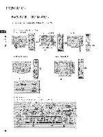
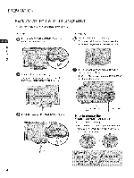
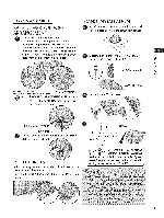
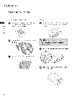
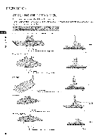
32/3 7/42LGSooH BACK COVERFORWIRE ARRANGEMENT STAND INSTALLATION Carefully place the TV screen side down on a cushioned surface to protect the screen from damage. // Connect the cables as necessary. To connect additional equipment, see the EXTERNAL EQUIPMENT SETUP section. Secure the power cable with the PROTECTIVE BRACKET/Screw or PLUG IN TYPE HOLDER for power code. It will help prevent the power cable from being removed by accident. Assemble the parts of the STAND BODY -0 _o with COVER BASE of the TV. m o......... _o BODY 0 z PROTECTIVE BRACKET (This feature is not available for all models.) PLUG IN TYPE HOLDER Install the CABLE MANAGEMENT CLIP as shown. If your TV has the CABLE HOLDER, install it as shown and bundle the cables. Assemble the TV as shown. BASE CABLE MANAGEMENT CABLE HOLDER O Put the cables inside the CABLE MANAGEMENT CLIP and snap it closed._ PROTECTION COVER After removing the stand, install the included protection cover over the hole for the stand. Press the PROTECTION hear it click. COVER into the TV until you 4 or J f _ _ Tighten the two of these four screws /-_ xZ x2 andthetwoTorxplusstarheadscrews | (provided as parts of the TV) to securethe TV. Tighten | the two Torx plus star head screwswith a star head dri- L,ver bit (not provided as parts of the TV). 15
-
 1
1 -
2
-
3
-
4
-
5
-
6
-
7
-
8
-
9
-
10
-
11
-
 12
12 -
 13
13 -
 14
14 -
 15
15 -
 16
16 -
 17
17 -
 18
18 -
 19
19 -
 20
20 -
 21
21 -
 22
22 -
23
-
24
-
25
-
26
-
27
-
28
-
29
-
30
-
31
-
32
-
33
-
34
-
35
-
36
-
37
-
38
-
39
-
40
-
41
-
42
-
43
-
44
-
45
-
46
-
47
-
48
-
49
-
50
-
51
-
52
-
53
-
54
-
55
-
56
-
57
-
58
-
59
-
60
-
61
-
62
-
63
-
64
-
65
-
66
-
67
-
68
-
69
-
70
-
71
-
72
-
73
-
74
-
75
-
76
-
77
-
78
-
79
-
80
-
81
-
82
-
83
-
84
-
85
-
86
-
87
-
88
-
89
-
90
 |
 |
