LG KU580 Service Manual
LG KU580 Manual
 |
View all LG KU580 manuals
Add to My Manuals
Save this manual to your list of manuals |
LG KU580 manual content summary:
- LG KU580 | Service Manual - Page 1
Service Manual Internal Use Only Service Manual KU580 Date: August, 2007 / Issue 1.0 Model : KU580 - LG KU580 | Service Manual - Page 2
Trouble 78 4.2 USB Trouble 79 4.3 SIM Detect Trouble 80 4.4 MicroSD card Trouble 81 4.5 Keypad And Touch key Trouble 82 4.6 Camera Trouble 85 4.7 Main LCD Trouble 89 4.8 Keypad Backlight Trouble 91 4.9 Folder ON/OFF Trouble 93 4.10 Audio Trouble 145 5. KU580 Download Setup Manual 157 6. - LG KU580 | Service Manual - Page 3
Table Of Contents LGE Internal Use Only -4- Copyright © 2007 LG Electronics. Inc. All right reserved. Only for training and service purposes - LG KU580 | Service Manual - Page 4
steps to maintain telephone service. D. Maintenance Limitations Maintenance limitations on the phones must be performed only by the manufacturer or its authorized agent. The user may not make any changes and/or repairs expect as specifically noted in this manual. Therefore, note that unauthorized - LG KU580 | Service Manual - Page 5
provide information such as the following to the end user. F. Pictures The pictures in this manual are for illustrative purposes only; your actual hardware may look slightly different. G. Interference and Attenuation A phone may interfere with sensitive laboratory equipment, medical equipment, etc - LG KU580 | Service Manual - Page 6
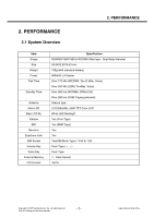
(GSM, Paging period=5) Intenna type 2.0"(320x240), 260K TFT Color LCD White LED Backlight Yes (Coin Type) Yes (SMD Type) Yes Yes Yes(SIM Block Type) : 3.0V & 1.8V Push Type ( + , - ) Push Type T - Flash Socket 18 Pin Copyright © 2007 LG Electronics. Inc. All right reserved. Only for training and - LG KU580 | Service Manual - Page 7
Environment(Accessory) Item Power * CLA : 12~24V (DC) Spec. Available power Min Typ. Max Unit 100 220 240 Vac Transmitter - GSM Mode No Item GSM DCS & PCS 100k~1GHz MS allocated 9k ~ 1GHz -39dBm © 2007 LG Electronics. Inc. All right reserved. Only for training and service purposes - LG KU580 | Service Manual - Page 8
2. PERFORMANCE No Item GSM DCS & PCS 30M ~ 1GHz MS allocated 30M~1GHz -36dBm 1G ~ 1710MHz -36dBm -30dBm Radiated 600kHz 1200kHz 1800kHz -22dB -24dB -24dB -27dB Copyright © 2007 LG Electronics. Inc. All right reserved. Only for training and service purposes -9- LGE Internal Use Only - LG KU580 | Service Manual - Page 9
PERFORMANCE No Item GSM DCS & PCS Frequency offset 800kHz 7 Intermodulation attenuation ±4 19 5 ±5 14 2 ±5 15 0 ±5 9 Burst timing Mask IN Mask IN LGE Internal Use Only - 10 - Copyright © 2007 LG Electronics. Inc. All right reserved. Only for training and service purposes - LG KU580 | Service Manual - Page 10
2. PERFORMANCE 2) Transmitter - WCDMA Mode No Item Specification 1 Maximum Output Power Class 3 : +24dBm(+1/-3dB) Class 4 : +21dBm(±2dB) 1M -49dBc@∆f=8.5~12.5MHz,1M Copyright © 2007 LG Electronics. Inc. All right reserved. Only for training and service purposes - 11 - LGE Internal Use Only - LG KU580 | Service Manual - Page 11
Magnitude (EVM) 17 Transmit OFF Power Specification 33dB@5MHz, ACP>-50dBm 43dB@10MHz, 1DPCCH) -15dB@SF=4.768Kbps, Multi-code transmission 3)Receiver - GSM Mode No Item GSM DCS & PCS 1 Sensitivity (TCH/FS Class LG Electronics. Inc. All right reserved. Only for training and service purposes - LG KU580 | Service Manual - Page 12
-band Blocking 6 Spurious Response 7 Intermodulation Characteristic 8 Spurious Emissions Specification -106.7 dBm(3.84 MHz) -25dBm(3.84MHz) -44dBm/3.84MHz 2170MHz, 3.84MHz Copyright © 2007 LG Electronics. Inc. All right reserved. Only for training and service purposes - 13 - LGE Internal Use Only - LG KU580 | Service Manual - Page 13
Carrier Freq. Tolerance 9 Carrier Frequency Drift 10 Out of Band Spurious Emissions Specification Class 2 : -6~4dBm Power density < 20dBm per 100kHz EIRP Option 2dB ≤ LGE Internal Use Only - 14 - Copyright © 2007 LG Electronics. Inc. All right reserved. Only for training and service purposes - LG KU580 | Service Manual - Page 14
2. PERFORMANCE 5.2) Receiver No Item Specification 1 Sensitivity single slot packets BER ≤ 0.1%@-70dBm 2 Sensitivity multi slot Maximum Input Level BER ≤ 0.1%@-20dBm Copyright © 2007 LG Electronics. Inc. All right reserved. Only for training and service purposes - 15 - LGE Internal Use Only - LG KU580 | Service Manual - Page 15
2. PERFORMANCE 2.4 Current Consumption (VT test : Speaker off, LCD backlight On) WCDMA GSM Stand by 280 Hours = 3.0 -87 ± 2 dBm -97 ± 2 dBm -107 ± 2 dBm -112 ± 2 dBm LGE Internal Use Only - 16 - Copyright © 2007 LG Electronics. Inc. All right reserved. Only for training and service purposes - LG KU580 | Service Manual - Page 16
2. PERFORMANCE 2.6 Battery Bar Indication BAR 4 → 3 (72%) BAR 3 → 2 (53%) BAR 2 → 1 (28%) BAR 1 → Icon 3min. Inverval) -3% 3.10 ±0.05V ↓ (WCDMA Talk) 3.20 ±0.05V ↓ (else) Copyright © 2007 LG Electronics. Inc. All right reserved. Only for training and service purposes - 17 - LGE Internal Use Only - LG KU580 | Service Manual - Page 17
Pressure Level No Test Item Specification NOM 1 Sending Loudness Rating 40dBPA under TDMA NOISE -.GSM: Power Level: 5 MS DCS: Power Level: 0 (Cell Power: -90 ~ -105dBm) 17 -.Acoustic(Max Vol.) MS/HEADSET SLR: 8±3dB LG Electronics. Inc. All right reserved. Only for training and service purposes - LG KU580 | Service Manual - Page 18
45˚C over) (GSM: It should be kept 3.7V in all power level WCDMA: It will not be kept 3.7V in some power level) Copyright © 2007 LG Electronics. Inc. All right reserved. Only for training and service purposes - 19 - LGE Internal Use Only - LG KU580 | Service Manual - Page 19
ETM), Instruction and Data (I&D)-cache, and I&DTCM - Access peripheral subsystems - Subscriber Identity Module (SIM) interface, IrDA®, Universal Serial Bus (USB), . LGE Internal Use Only - 20 - Copyright © 2007 LG Electronics. Inc. All right reserved. Only for training and service purposes - LG KU580 | Service Manual - Page 20
Purpose I/O (GPIO) Interface - External Memory Interface that supports NAND, NOR, PSRAM, SDRAM, - JTAG - RTC - ETM (in Prototype Package) Figure 3-1-1 KU580 Block Diagram Copyright © 2007 LG Electronics. Inc. All right reserved. Only for training and service purposes - 21 - LGE Internal Use Only - LG KU580 | Service Manual - Page 21
Configuration of KU580 • Data Communication - IrDA ® (SIR) - UARTs (ACB, EDB (RS232)) - Slave USB • Package - 12 by 12 mm 344 balls, 0.5mm pitch FPBGA Production Package LGE Internal Use Only - 22 - Copyright © 2007 LG Electronics. Inc. All right reserved. Only for training and service purposes - LG KU580 | Service Manual - Page 22
3.1.3 Hardware Architecture A. Block Diagram 3. Technical Brief Figure 3-1-3. Access system of Ericsson DB3100 Figure 3-1-4. Application system of Ericsson DB3100 Copyright © 2007 LG Electronics. Inc. All right reserved. Only for training and service purposes - 23 - LGE Internal Use Only - LG KU580 | Service Manual - Page 23
Subsystem The digital baseband controller includes hardware that supports mobile terminal peripherals such as a MMC, SD, UART, I2C, USB, keypad, and infrared. Collectively, this hardware Use Only - 24 - Copyright © 2007 LG Electronics. Inc. All right reserved. Only for training and service purposes - LG KU580 | Service Manual - Page 24
data to a display. The XGAM also provides support for connecting a Camera module. The visual data responsible for clock generation and clock and reset distribution within the digital baseband controller, as © 2007 LG Electronics. Inc. All right reserved. Only for training and service purposes Figure - LG KU580 | Service Manual - Page 25
) SIM card bidirectional data line SIM card reference clock SIM card async/sync reset Table 3-1-2. SIM Interface Asta SIMDAT0 SIMCLK0 SIMRST0 VDD E 10K SIMVCC Veronica SDAT Internal Use Only - 26 - Copyright © 2007 LG Electronics. Inc. All right reserved. Only for training and service purposes - LG KU580 | Service Manual - Page 26
UART0 Name ACC_UART_RX ACC_UART_TX UART1 APP_UART_RX APP_UART_TX Table 3- 1- 3. UART Interface Note ACC Receive Data ACC Transmit Data APP Receive Data APP Transmit Data Copyright © 2007 LG Electronics. Inc. All right reserved. Only for training and service purposes - 27 - LGE Internal Use Only - LG KU580 | Service Manual - Page 27
Map, describing application, I/O state, and enable level are shown in below table. LGE Internal Use Only Table 3-1-4. Asta ACC GPIO Map Table - 28 - Copyright © 2007 LG Electronics. Inc. All right reserved. Only for training and service purposes - LG KU580 | Service Manual - Page 28
Input/Output) map The USB block supports the implementation of a "full-speed" device fully compliant to USB 2.0 Access GPIO GPIO Input Input Input/output Input/output Copyright © 2007 LG Electronics. Inc. All right reserved. Only for training and service purposes - 29 - LGE Internal Use Only - LG KU580 | Service Manual - Page 29
signal USB data0 USB data1 USB data2 USB data3 USB data4 USB data5 USB data6 USB data7 USB chip select Power supply for Asta USB block Table 3-1-6. USB Signal Interface of Asta LGE Internal Use Only - 30 - Copyright © 2007 LG Electronics. Inc. All right reserved. Only for training and service - LG KU580 | Service Manual - Page 30
0 VBUS_USB_TRX USB_XTAL1 GND3 E4 GND2 D2 GND1 C5 C430 0.1u R438 1% 12K C431 0.1u C432 4.7u C433 2.2u 0.1u C428 4.7u C429 Figure 3-1-9. Schematic of USB Transceiver Copyright © 2007 LG Electronics. Inc. All right reserved. Only for training and service purposes - 31 - LGE Internal Use Only - LG KU580 | Service Manual - Page 31
0.1u U500 TK60012BM5 1 6 VDD IO_VDD 2 5 GND1 GND2 3 NC 4 OUT C501 0.1u APP_GP02_FLIPSENSE Figure 3-1-10. Slider On/Off Detector LGE Internal Use Only - 32 - Copyright © 2007 LG Electronics. Inc. All right reserved. Only for training and service purposes - LG KU580 | Service Manual - Page 32
3. Technical Brief 3.1.11 Bluetooth Interface KU580 supports Bluetooth operation using ST' STLC2590C Bluetooth module. A. without having the master clock running. Copyright © 2007 LG Electronics. Inc. All right reserved. Only for training and service purposes - 33 - LGE Internal Use Only - LG KU580 | Service Manual - Page 33
specification compliance: V2.0 + EDR. - Point-to-point, point-to-multi-point (up to 7 slaves) and scatternet capability - Support download • Supports Pitch-Period Error Concealment (PPEC) • Efficient and flexible support LG Electronics. Inc. All right reserved. Only for training and service purposes - LG KU580 | Service Manual - Page 34
up to 128 bits key • Single power supply with internal regulators for core voltage generation • Supports 1.65 to 2.85 Volts IO systems • Auto calibration (VCO, Filters) Copyright © 2007 LG Electronics. Inc. All right reserved. Only for training and service purposes - 35 - LGE Internal Use Only - LG KU580 | Service Manual - Page 35
signal of Asta controls STLC2590C reset. • SPI - Connected to SPI of Asta - HCI interface between Asta and STLC2590C • PCM - Audio signal interface between Asta/Veronica and STLC2590C • ANT - 2.4GHz, 50 ohm matching LGE Internal Use Only - 36 - Copyright © 2007 LG Electronics. Inc. All right - LG KU580 | Service Manual - Page 36
Technical Brief 3.1.12 MicroSD Interface card KU580 supports the MicroSD card interface as external memory card. MicroSD card has 4-data line, so KU580 uses 4-data line. All control Interface Copyright © 2007 LG Electronics. Inc. All right reserved. Only for training and service purposes - 37 - - LG KU580 | Service Manual - Page 37
User presses END key and then ONSWAn signal is changed to Low. ➁ Veronica initiates the internal oscillator and powers on the regulators. ➂ Veronica generates a power for Asta. ➃ Veronica releases the power reset © 2007 LG Electronics. Inc. All right reserved. Only for training and service purposes - LG KU580 | Service Manual - Page 38
# KB_shp KEYOUT3 KEYOUT4 Figure 3-1-14. MAIN PCB KeyPad Circuit ESD9X5.0ST5G ZD508 INSTPAR ESD9X5.0ST5G KEYOUT0 CN502 1 2 3 4 5 ONSWA_n CN503 1 2 3 4 KEYOUT4 KEYIN5 Copyright © 2007 LG Electronics. Inc. All right reserved. Only for training and service purposes - 39 - LGE Internal Use Only - LG KU580 | Service Manual - Page 39
SENSE3 UP LEFT OK DOWN RIGHT KEYOUT3 KEYOUT4 TP103 SENSE0 TP104 SENSE1 Figure 3-1-15. KEY PCB KeyPad Circuit LGE Internal Use Only - 40 - Copyright © 2007 LG Electronics. Inc. All right reserved. Only for training and service purposes - LG KU580 | Service Manual - Page 40
Description The Graphics Accelerator Module (GAM) subsystem provides hardware support in the creation of visual imagery and the transfer of • CDI: camera data interface. Copyright © 2007 LG Electronics. Inc. All right reserved. Only for training and service purposes - 41 - LGE Internal Use Only - LG KU580 | Service Manual - Page 41
reset signal to GRAPHCON, GRAM, PDI and CDI. The reset memory (GRAM) in order to support display screen sizes of QCIF + executes 16-bit instruction words to individually control the store up to 64 instructions. The CPU transfers all configured at the software build stage, to support either parallel interface such - LG KU580 | Service Manual - Page 42
input or high impedance during mobile equipment reset and start. In this case, it must have pull-down to ground. The camera module reset signal is an output to the camera module. Copyright © 2007 LG Electronics. Inc. All right reserved. Only for training and service purposes - 43 - LGE Internal - LG KU580 | Service Manual - Page 43
SYSCLK0 C505 33p C506 NA C502 NA C503 1u C504 1u Figure 3-2-3. 2M Camera Connector(24Pin - Main Board) LGE Internal Use Only - 44 - Copyright © 2007 LG Electronics. Inc. All right reserved. Only for training and service purposes - LG KU580 | Service Manual - Page 44
1 20 2 19 3 18 4 17 5 16 6 15 7 14 8 13 9 12 10 11 CI_RES_n APP_I2C_SCL APP_I2C_SDA CI_HSYNC CI_VSYNC CI_D7 CI_D6 Figure 3-2-5. VGA LCD FPCB Connector Copyright © 2007 LG Electronics. Inc. All right reserved. Only for training and service purposes - 45 - LGE Internal Use Only - LG KU580 | Service Manual - Page 45
and receive 32.2MHz pixel clock(15fps), vertical sync signal, horizontal sync signal, reset signal and 8bits YUV data from camera module. The camera module is controlled LCD FPCB) LGE Internal Use Only - 46 - Copyright © 2007 LG Electronics. Inc. All right reserved. Only for training and service - LG KU580 | Service Manual - Page 46
for only 2M digital core. It's derived from AB3000 and controlled by camera driver file. C12 VDD_A B11 EXTLDO F12 VDD_D D12 VDD_E A11 VDD_C B12 VDD_H A9 VDD_F Headph MICRON 1.8V, SS 1.5V to DB3100 analog to SD Card and LCD to Bluetooth to AB3000 RTC module VBUCK_FB VCORE to DB3100 CORE 0 BAT600 - LG KU580 | Service Manual - Page 47
262K Color TFT LCD 4 White LEDs Table 3-2-3. Device in LCD Module LCD Module is connected to Key PCB with 40-pin Connector in sub PCB. The LCD is controlled by 8bit PDI(Parallel Data Interface) in DB3100. No. Signal 1 GND 2 LED C1 3 LED C4 4 LED A 5 GND 6 RESET 7 GND 8 D15 9 D13 - LG KU580 | Service Manual - Page 48
Main Board VGA Camera Figure 3-2-8. LCD Module Block Diagram 2M Camera 262K TFT LCD 320 X 240 pixels Main LCD Driver IC S6D0171 Figure 3-2-9. LCD Module(Main LCD) Copyright © 2007 LG Electronics. Inc. All right reserved. Only for training and service purposes - 49 - LGE Internal Use - LG KU580 | Service Manual - Page 49
Backlight Illumination There are 4 white LEDs in LCD Backlight circuit which is driven by Charge Pump(MAX8631). APP_GP10_BL_CTRL is LED Interface and Backlight Circuit LGE Internal Use Only - 50 - Copyright © 2007 LG Electronics. Inc. All right reserved. Only for training and service purposes - LG KU580 | Service Manual - Page 50
interface consists of PCM encoding and decoding circuitry, microphone amplifiers and earphone drivers. The PCM encoder and decoder blocks are two-channel, 16-bit ports. Copyright © 2007 LG Electronics. Inc. All right reserved. Only for training and service purposes - 51 - LGE Internal Use Only - LG KU580 | Service Manual - Page 51
SPK_RCV_P SPK_RCV_N R632 100K C634 220n R633 NA R634 1% 39K ACC_GP12_LSPK_EN R635 0 R636 51K Figure 3-3-3 . Audio Section scheme LGE Internal Use Only - 52 - Copyright © 2007 LG Electronics. Inc. All right reserved. Only for training and service purposes - LG KU580 | Service Manual - Page 52
BEARP/BEARN MIC1P/MIC1N SPKRP/SPKRN MIC2P/MIC2N AUXO1/AUXO2 MIC1P/MIC1N SPKRP/SPKRN SPKRP/SPKRN SPKR/SPKN AUXO1/AUXO2 Table 3-3-1. Audio Mode Copyright © 2007 LG Electronics. Inc. All right reserved. Only for training and service purposes - 53 - LGE Internal Use Only - LG KU580 | Service Manual - Page 53
a serial input stream of linear PCM coded speech. The receive bandpass filter is the . Both the earphone driver and one of the auxiliary drivers can simultaneously provide an Phone LGE Internal Use Only - 54 - Copyright © 2007 LG Electronics. Inc. All right reserved. Only for training and service - LG KU580 | Service Manual - Page 54
from the Audio Mixer must be performed in 8 kHz mono, since this is supported by the Voice mode. Due to performance reasons it may not be possible to decode is displayed on Main LCD. Copyright © 2007 LG Electronics. Inc. All right reserved. Only for training and service purposes - 55 - LGE Internal - LG KU580 | Service Manual - Page 55
) This section provides a detailed description of the MIDI and WAV-file functions. Figure 3-3-6, External MIDI path In Figure 2-4-6, External MIDI path ) → Speaker(8Ω) LGE Internal Use Only - 56 - Copyright © 2007 LG Electronics. Inc. All right reserved. Only for training and service purposes - LG KU580 | Service Manual - Page 56
description of the MP3 file functions. Figure 3-3-7. MP3 Scheme MP3 function supports PCM 44/48KHz sampling rate.The PCM44/48 RX-path is intended to be used as a audio amp and one speaker. Copyright © 2007 LG Electronics. Inc. All right reserved. Only for training and service purposes - 57 - LGE - LG KU580 | Service Manual - Page 57
3.3.8 Audio Main Component There are 4 components in KU580 schematic Diagram. Part Number marked on KU580 Schematic Diagram. NO ITEM 1 Speaker/Receiver 2 MIC sound LGE Internal Use Only - 58 - Copyright © 2007 LG Electronics. Inc. All right reserved. Only for training and service purposes - LG KU580 | Service Manual - Page 58
GPA6 VBACKUP Description Radio temperature sense Loop voltage sense Reference voltage for PAM Lock inform Headset detect Backup battery Table 3-4-1. GPADC channel spec Copyright © 2007 LG Electronics. Inc. All right reserved. Only for training and service purposes - 59 - LGE Internal Use Only - LG KU580 | Service Manual - Page 59
3-5-2. Battery charging block diagram Type Analog Analog Unused VBAT VBAT Description Current sensing input positive Current sensing input negative Table 3-5-1. Charger Control channel spec - 60 - Copyright © 2007 LG Electronics. Inc. All right reserved. Only for training and service purposes - LG KU580 | Service Manual - Page 60
is connected in series with the battery. The voltage across the resistor, equivalent to the current entering/leaving the battery, is integrated using an ADC block 3-5-2. Fuel Gauge channel spec Copyright © 2007 LG Electronics. Inc. All right reserved. Only for training and service purposes - 61 - - LG KU580 | Service Manual - Page 61
Fig 3-5-5. Battery Temperature Measurement D601 Name BDATA Type Digital Input/Output Unused Unconnected Table 3-5-3 BDATA channel spec Description current output LGE Internal Use Only - 62 - Copyright © 2007 LG Electronics. Inc. All right reserved. Only for training and service purposes - LG KU580 | Service Manual - Page 62
4.2 ~3.88 (V) 100~66 (%) 3.87 ~3.81 (V) 65~44 (%) 3.80 ~3.74 (V) 3.73 ~3.59 (V) 43~25 (%) 24~3 (%) Fig. 3-5-7 Battery Block Indication 3.58 ~3.20 (V) 2~0 (%) Copyright © 2007 LG Electronics. Inc. All right reserved. Only for training and service purposes - 63 - LGE Internal Use Only - LG KU580 | Service Manual - Page 63
current 30 50 60 mA Table. 3-5-4. Trickle charging spec Normal charging When the VBAT voltage is within limits VBAT voltage. This charging method prevents the battery voltage to go above the charge set in © 2007 LG Electronics. Inc. All right reserved. Only for training and service purposes - LG KU580 | Service Manual - Page 64
normal charging specification, the battery voltage, VBAT, is maintained at 3.7V. • Under 0°C : Extended temperature • From 0°C to 45°C : Normal charging temperature • Over 45°C : Extended temperature Copyright © 2007 LG Electronics. Inc. All right reserved. Only for training and service purposes - LG KU580 | Service Manual - Page 65
. It provides power for the 32 kHz oscillator and the real-time clock (RTC). Table. 3-6-1. LDO and Buck LGE Internal Use Only - 66 - Copyright © 2007 LG Electronics. Inc. All right reserved. Only for training and service purposes - LG KU580 | Service Manual - Page 66
RF Technical Description 3.7.1 General Description The RF platform of KU580 supports two different communication modes (WCDMA/GSM modes) including four diagram of RF part Copyright © 2007 LG Electronics. Inc. All right reserved. Only for training and service purposes - 67 - LGE Internal Use Only - LG KU580 | Service Manual - Page 67
point is controlled by a D/Aconverter in the W-CDMA radio circuit. These DACs are controlled through the 3-wire-bus LGE Internal Use Only - 68 - Copyright © 2007 LG Electronics. Inc. All right reserved. Only for training and service purposes - LG KU580 | Service Manual - Page 68
amplified with provision of 31 x 1 dB steps and DC offset compensation. The zero IF output buffer provides close rail-to-rail outputs signal. Copyright © 2007 LG Electronics. Inc. All right reserved. Only for training and service purposes - 69 - LGE Internal Use Only - LG KU580 | Service Manual - Page 69
ranges that are selected internally depending on the frequency programming. The calibration is done on each low to high logical transition of the SYNON bit in the control LGE Internal Use Only - 70 - Copyright © 2007 LG Electronics. Inc. All right reserved. Only for training and service purposes - LG KU580 | Service Manual - Page 70
is a fully matched 10-pad surface mount module developed for Wideband Code Division Multiple Access (WCDMA) applications. This small and efficient power PAM schematic Copyright © 2007 LG Electronics. Inc. All right reserved. Only for training and service purposes - 71 - LGE Internal Use Only - LG KU580 | Service Manual - Page 71
slot class 12 (4+4=5) Dual Transfer Mode (DTM) class 9 (3+2=5) Zero-IF receiver • Polar modulation transmitter Figure 3-7-7. GSM Transceiver Architecture LGE Internal Use Only - 72 - Copyright © 2007 LG Electronics. Inc. All right reserved. Only for training and service purposes - LG KU580 | Service Manual - Page 72
1900 MHz. The complete receiver with four Low Noise Amplifiers (LNAs), one for each supported band, is integrated on chip. After the down-conversion, the in-phase and filters in front of the LNAs. One filter is required per supported frequency band. The digital output signals are sent over a serial - LG KU580 | Service Manual - Page 73
generated for use in the W-CDMA circuit. This output is activated by a control signal in the digital bus. LGE Internal Use Only - 74 - Copyright © 2007 LG Electronics. Inc. All right reserved. Only for training and service purposes - LG KU580 | Service Manual - Page 74
a single circuit containing: - Antenna Switch with support for W-CDMA band 1 - Power amplifiers for ; one at a time in the GSM, DCS, and PCS bands). In W-CDMA systems, the transmitter and the receiver 2007 LG Electronics. Inc. All right reserved. Only for training and service purposes - 75 - LG KU580 | Service Manual - Page 75
comprising GSM850/900, DCS1800, and PCS1900 operation. The FEM also supports Class 12 General Packet Radio Service (GPRS) multi-slot operation, Polar EDGE modulation, and provides single Only - 76 - Copyright © 2007 LG Electronics. Inc. All right reserved. Only for training and service purposes - LG KU580 | Service Manual - Page 76
performed by the analog baseband controller. The control flow for the RF system is shown in Figure 3-7-11. Figure 3-7-11. RF Control Flow Copyright © 2007 LG Electronics. Inc. All right reserved. Only for training and service purposes - 77 - LGE Internal Use Only - LG KU580 | Service Manual - Page 77
(TP412) level is low when END key pressed. Yes No change main battery No Follow the keypad Trouble shooting guide Check the voltage. VDD_A (R605) 2.75V VDD_C (R608) 2.75V VDD_D Use Only - 78 - Copyright © 2007 LG Electronics. Inc. All right reserved. Only for training and service purposes - LG KU580 | Service Manual - Page 78
same to battery? Yes ACC_GP20_USB_CS_PD is 1.8V? Yes Change main board No Check host USB port or USB cable No Resolder or change R430 No Resolder or change U402 R436 U402 R436 < Main Board - Top side > Copyright © 2007 LG Electronics. Inc. All right reserved. Only for training and service - LG KU580 | Service Manual - Page 79
SHOOTING 4.3 SIM Detect Trouble • SIM control path - Asta generates SIM interface signals(1.8V level) to Veronica Change main board J40J0400 < Main Board - Bottom side > LGE Internal Use Only - 80 - Copyright © 2007 LG Electronics. Inc. All right reserved. Only for training and service purposes - LG KU580 | Service Manual - Page 80
SHOOTING 4.4 MicroSD card Trouble START Re-insert MicroSD card Yes MicroSD card work well? N o o Change main board Yes Finish R418 S400 < Main Board - Bottom side > Copyright © 2007 LG Electronics. Inc. All right reserved. Only for training and service purposes - 81 - LGE Internal Use Only - LG KU580 | Service Manual - Page 81
4.5 Keypad And Touch key Trouble 4.5.1 Keypad Trouble START Press the Keypad Keypad operates well? NO Check side key short? NO 1 NO Change Main Board YES Finish LGE Internal Use Only - 82 - Copyright © 2007 LG Electronics. Inc. All right reserved. Only for training and service purposes - LG KU580 | Service Manual - Page 82
~ #59 KEYIN5 KEYIN4 KEYIN3 1 Pin #18 ~ #19 KEYOUT3 KEYOUT4 Pin #22 ~ #24 KEYOUT5 KEYOUT4 KEYOUT3 1 40 CN100 20 21 < Sub Board ñ Bottom side > Copyright © 2007 LG Electronics. Inc. All right reserved. Only for training and service purposes - 83 - LGE Internal Use Only - LG KU580 | Service Manual - Page 83
SHOOTING 4.5.2 Touch key Trouble START Reboot the phone Yes Touch key work well? N o Board to Board CN reconnect (Main : CN501, Sub 20 21 < Sub Board - Bottom side > LGE Internal Use Only - 84 - Copyright © 2007 LG Electronics. Inc. All right reserved. Only for training and service purposes - LG KU580 | Service Manual - Page 84
or C108(sub)=2.8V? Pin5 of U101 or C109(sub)=1.8V? YES Change 2M Camera NO Follow the Power On Trouble Shooting NO Change U101 NO 2M Camera Works Change the Main Board Copyright © 2007 LG Electronics. Inc. All right reserved. Only for training and service purposes - 85 - LGE Internal Use Only - LG KU580 | Service Manual - Page 85
4. TROUBLE SHOOTING CN500 1 24 pin 2M Camera Connector in Main Board 2 C109 C108 U101 LGE Internal Use Only Charge Pump in Sub Board - 86 - Copyright © 2007 LG Electronics. Inc. All right reserved. Only for training and service purposes - LG KU580 | Service Manual - Page 86
VGA Camera NO VGA Camera Operation OK? YES VGA Camera Works Follow the Power On Trouble Shooting Change U101 NO Change the Camera&LCD FPCB NO Change the Main Board Copyright © 2007 LG Electronics. Inc. All right reserved. Only for training and service purposes - 87 - LGE Internal Use Only - LG KU580 | Service Manual - Page 87
4. TROUBLE SHOOTING CN5C0N1501 Main Board 70 pin BtoB Connector 1 CN101 LCD FPCB 20 pin VGA Connector 2 C109 C108 U101 Charge Pump in Sub Board LGE Internal Use Only - 88 - Copyright © 2007 LG Electronics. Inc. All right reserved. Only for training and service purposes - LG KU580 | Service Manual - Page 88
(sub PCB) And 40pin LCD connector (sub PCB) LCD Display OK? YES The LCD Works NO Change LCD FPCB or Key PCB YES Change LCD Module LCD Display OK? NO Change the Main Board Copyright © 2007 LG Electronics. Inc. All right reserved. Only for training and service purposes - 89 - LGE Internal - LG KU580 | Service Manual - Page 89
4. TROUBLE SHOOTING 1 CNC5N05101 Main Board 70 pin BtoB Connector LCD FPCB 40 pin BtoB Connector 2 sub PCB 40 pin LCD Connector LGE Internal Use Only - 90 - Copyright © 2007 LG Electronics. Inc. All right reserved. Only for training and service purposes - LG KU580 | Service Manual - Page 90
? NO 1 Backlight Control Signal is 2.8V at R517? YES 2 Resolder or Change Q501 Keypad Backlight Works? YES Finish NO NO Change Main Board Copyright © 2007 LG Electronics. Inc. All right reserved. Only for training and service purposes - 91 - LGE Internal Use Only - LG KU580 | Service Manual - Page 91
4. TROUBLE SHOOTING ACC_GP16_KEY_LED_ON LGE Internal Use Only R531 100K R518 36 R532 36 R517 2.2K 123 654 Q501 EMX18 2 R517 Q501 1 - 92 - VBAT Copyright © 2007 LG Electronics. Inc. All right reserved. Only for training and service purposes R519 R520 R521 R522 R523 R524 R525 R526 R527 - LG KU580 | Service Manual - Page 92
SHOOTING 4.9 Folder ON/OFF Trouble START 1 Check magnet No Insert magnet in lower slide Yes Turn the power keypad Slide OK? Yes Finished No Change Main board Copyright © 2007 LG Electronics. Inc. All right reserved. Only for training and service purposes - 93 - LGE Internal Use Only - LG KU580 | Service Manual - Page 93
TK60012BM5 1 6 VDD IO_VDD 2 5 GND1 GND2 3 NC 4 OUT C501 0.1u APP_GP02_FLIPSENSE 1 Be sure that magnet is here U500 2 R608 3 LGE Internal Use Only - 94 - Copyright © 2007 LG Electronics. Inc. All right reserved. Only for training and service purposes - LG KU580 | Service Manual - Page 94
on main board → 3. LCD FPCB → 4. Speaker/Receiver ♣ Note : It is recommended that engineer should check the soldering of R, L, C along the corresponding path before every step. Copyright © 2007 LG Electronics. Inc. All right reserved. Only for training and service purposes - 95 - LGE Internal - LG KU580 | Service Manual - Page 95
Change the LCD FPCB YES Is the soldering ot the 3 receiver OK? YES Can you hear sine wave out of the receiver ? YES END NO Resolder Receiver NO Change the Receiver LGE Internal Use Only - 96 - Copyright © 2007 LG Electronics. Inc. All right reserved. Only for training and service purposes - LG KU580 | Service Manual - Page 96
4. TROUBLE SHOOTING A SIDE CN501 2 Pin 67, 69 1 ZD500,ZD501 LCD FPCB 3 Copyright © 2007 LG Electronics. Inc. All right reserved. Only for training and service purposes - 97 - LGE Internal Use Only - LG KU580 | Service Manual - Page 97
4. TROUBLE SHOOTING 1 2 Measured 1khz Sine Wave Signal 3 LGE Internal Use Only Measured 1khz Sine Wave Signal - 98 - Copyright © 2007 LG Electronics. Inc. All right reserved. Only for training and service purposes - LG KU580 | Service Manual - Page 98
4. TROUBLE SHOOTING 4.10.2. Speaker (Voice Loud Speaker,Midi, MP3,Key Tone) Signals to the check the soldering of R, L, C along the corresponding path before every step. Copyright © 2007 LG Electronics. Inc. All right reserved. Only for training and service purposes - 99 - LGE Internal Use Only - LG KU580 | Service Manual - Page 99
4. TROUBLE SHOOTING START Connect the phone to network Equipment and setup call Setup 1KHz tone out NO 1 Does the sine a speaker ? NO Change each Speaker YES END LGE Internal Use Only - 100 - Copyright © 2007 LG Electronics. Inc. All right reserved. Only for training and service purposes - LG KU580 | Service Manual - Page 100
2 U600 4. TROUBLE SHOOTING B SIDE U600 U600 1 C633,C634 B SIDE 3 C633, R691 4 ZD500,ZD501 Copyright © 2007 LG Electronics. Inc. All right reserved. Only for training and service purposes - 101 - LGE Internal Use Only - LG KU580 | Service Manual - Page 101
4. TROUBLE SHOOTING 5 Measured 1khz Sine Wave Signal LGE Internal Use Only - 102 - Copyright © 2007 LG Electronics. Inc. All right reserved. Only for training and service purposes - LG KU580 | Service Manual - Page 102
4. TROUBLE SHOOTING 4.10.3. Microphone (Voice call, Voice Recorder, Video Recorder) • Microphone Signal Flow R600 on main board → - CC623,C625 on main board → - Veronoca Copyright © 2007 LG Electronics. Inc. All right reserved. Only for training and service purposes - 103 - LGE Internal Use Only - LG KU580 | Service Manual - Page 103
4. TROUBLE SHOOTING START Check the MIC bias level at the pad of MIC Is the level of MIC+ AND MIC- 1 2. again, chage the main Bíd No Does it work properly ? YES END LGE Internal Use Only - 104 - Copyright © 2007 LG Electronics. Inc. All right reserved. Only for training and service purposes - LG KU580 | Service Manual - Page 104
4. TROUBLE SHOOTING 1 C623 B SIDE Copyright © 2007 LG Electronics. Inc. All right reserved. Only for training and service purposes - 105 - LGE Internal Use Only - LG KU580 | Service Manual - Page 105
4. TROUBLE SHOOTING 2 Measured Some Noise Signal LGE Internal Use Only - 106 - Copyright © 2007 LG Electronics. Inc. All right reserved. Only for training and service purposes - LG KU580 | Service Manual - Page 106
4. TROUBLE SHOOTING 4.10.4. Headset Receiver (Voice call, Video Telephony,MP3 ) START Connect the phone to network Equipment and setup call Setup 1KHz tone out 1 Insert Headset. NO Does the Headset icon display Does the level of R429 NO on the main LCD? under 0.5Volt ? YES YES YES 2 - LG KU580 | Service Manual - Page 107
4. TROUBLE SHOOTING 4.10.5. Headset MIC(Voice call, Video Telephony ) START Insert Headset. NO Does the Headset icon display on the main LCD? YES 5 Check the signal level at Use Only - 108 - Copyright © 2007 LG Electronics. Inc. All right reserved. Only for training and service purposes - LG KU580 | Service Manual - Page 108
4. TROUBLE SHOOTING 4.10.6. Headset B SIDE CN400 6 R679,R680 1,4 R627 2,4,5 R429 8 C426 B SIDE 7 CN600 5 C622,C625 3 C643,C644 Copyright © 2007 LG Electronics. Inc. All right reserved. Only for training and service purposes - 109 - LGE Internal Use Only - LG KU580 | Service Manual - Page 109
to the phone • Trouble Shooting Procedure - Check the charger connecter - Check the Charging current Path - Check the battery H1 VBAT_D E1 CHSENSE+ F2 CHSENSE- E2 CHREG F3 DCIO LGE Internal Use Only - 110 - Copyright © 2007 LG Electronics. Inc. All right reserved. Only for training and service - LG KU580 | Service Manual - Page 110
I/O connector YES NO 2 Is the TA voltage 4.6V? YES Change TA Is it charging properly 3 after changing Q600? NO Change the board YES END Trouble Shooting - Charging Copyright © 2007 LG Electronics. Inc. All right reserved. Only for training and service purposes - 111 - LGE Internal Use Only - LG KU580 | Service Manual - Page 111
4. TROUBLE SHOOTING 1 2 3 Main Board - I/O connector and FET LGE Internal Use Only - 112 - Copyright © 2007 LG Electronics. Inc. All right reserved. Only for training and service purposes - LG KU580 | Service Manual - Page 112
4. TROUBLE SHOOTING 4.12 Checking Bluetooth Block ** BT - Bluetooth Copyright © 2007 LG Electronics. Inc. All right reserved. Only for training and service purposes - 113 - LGE Internal Use Only - LG KU580 | Service Manual - Page 113
> MCLK (C828) VBT27 (C832) Bluetooth chip Output (L800) LGE Internal Use Only Bluetooth Antenna (ANT400) VBT18 (C837) - 114 - Copyright © 2007 LG Electronics. Inc. All right reserved. Only for training and service purposes - LG KU580 | Service Manual - Page 114
voltage level VBT18 (C603) with Oscilloscope About 2.75V? No Check Veronica (U603) Yes No About 1.8V? Yes Check Veronica (U603) Check Next Stage Copyright © 2007 LG Electronics. Inc. All right reserved. Only for training and service purposes - 115 - LGE Internal Use Only - LG KU580 | Service Manual - Page 115
4. TROUBLE SHOOTING 4.12.2 Checking Bluetooth Block MCLK (C828) VBT27 (C832) Bluetooth chip Output (L800) Bluetooth Antenna Yes Check Next Stage Change BT Chip (U401) LGE Internal Use Only - 116 - Copyright © 2007 LG Electronics. Inc. All right reserved. Only for training and service purposes - LG KU580 | Service Manual - Page 116
WCDMA Power Coupler WCDMA PA WCDMA DC/DC Converter WCDMA Rx SAW Filter WCDMA Tx SAW Filter WCDMA Transceiver (RF3100) Bluetooth Clock Buffer Copyright © 2007 LG Electronics. Inc. All right reserved. Only for training and service purposes - 117 - LGE Internal Use Only - LG KU580 | Service Manual - Page 117
4. TROUBLE SHOOTING 4.14 Procedure to check start Oscilloscope setting 1. Check Power Source Block 2. Check VCXO 62, -60dBm setting 5. Check GSM Block Redownload SW, Cal LGE Internal Use Only - 118 - Copyright © 2007 LG Electronics. Inc. All right reserved. Only for training and service purposes - LG KU580 | Service Manual - Page 118
4. TROUBLE SHOOTING 4.15 Checking Common Power Source Block Step 2 GSM PAM Block Step 3 WCDMA PAM Block Step 1 PAM VBAT Block WCDMA DC/DC VBAT GSM PA VBAT (Bottom) Figure 4-3. Common Source Block Copyright © 2007 LG Electronics. Inc. All right reserved. Only for training and service purposes - 119 - LG KU580 | Service Manual - Page 119
4. TROUBLE SHOOTING 4.15.1 Step 1 Check point (C618) C103 C102 C117 Figure 4-4. Step 1 : VBAT Block ➀ Check point (CN600 Block ➄ Check The PowerSupply Change Board LGE Internal Use Only - 120 - Copyright © 2007 LG Electronics. Inc. All right reserved. Only for training and service purposes - LG KU580 | Service Manual - Page 120
4. TROUBLE SHOOTING 4.15.2 Step 2 C103 C102 GGSSMMPPAAMM (Bottom) Figure 4-6. Step 2 : GSM PAM Block ➁ In Power Source Block ➄ Check The PowerSupply Change Board Copyright © 2007 LG Electronics. Inc. All right reserved. Only for training and service purposes - 121 - LGE Internal Use Only - LG KU580 | Service Manual - Page 121
4. TROUBLE SHOOTING 4.15.3 Step 3 Check point (C618) DC/DC Converter WCDMA PAM C117 Figure 4-7. Step 3 :WCDMA PAM Source Block ➄ Check the PowerSupply Change Board LGE Internal Use Only - 122 - Copyright © 2007 LG Electronics. Inc. All right reserved. Only for training and service purposes - LG KU580 | Service Manual - Page 122
4. TROUBLE SHOOTING 4.15.4 Checking VCC R607 (VDD_E) AB3000 R605 (VDD_A) (Bottom) Figure 4-9-1. Power for Radio ASIC ➃ OK See The Next Part Check the Vincenne2 Copyright © 2007 LG Electronics. Inc. All right reserved. Only for training and service purposes - 123 - LGE Internal Use Only - LG KU580 | Service Manual - Page 123
4. TROUBLE SHOOTING 4.16 Checking VCXO Block The reference frequency (26MHz) from U200(GSM Transceiver Digital Base Band (DB3100) Figure 4-12. Bottom Oscilloscope Notebook to send TP command Phone Figure 4-13. Connection for Checking VCXO Block LGE Internal Use Only - 124 - Copyright © 2007 - LG KU580 | Service Manual - Page 124
4. TROUBLE SHOOTING Check 1. Crystal and RF3000(GSM Transceiver) part If you already check this Figure 4-14-2. Schematic (Crystal Part) Figure 4-15. 26MHz at R211 Copyright © 2007 LG Electronics. Inc. All right reserved. Only for training and service purposes - 125 - LGE Internal Use Only - LG KU580 | Service Manual - Page 125
4. TROUBLE SHOOTING Check 2. 26MHz at WCDMA TX part C133 Figure 4-16-1. Test point (26MHz at TX part) 11 Schematic (26MHz at TX part) C133 LGE Internal Use Only Figure 4-17. 26MHz at C133 - 126 - Copyright © 2007 LG Electronics. Inc. All right reserved. Only for training and service purposes - LG KU580 | Service Manual - Page 126
4. TROUBLE SHOOTING Check 3. 26MHz at BB part R211 RF_CTRL_CLK WCLK MCLK MCLK R211 R211 120K . Schematic (26MHz at BB Part) W14 MCLK Y16 0 Figure 4-20. 26MHz at R211 Copyright © 2007 LG Electronics. Inc. All right reserved. Only for training and service purposes - 127 - LGE Internal Use Only - LG KU580 | Service Manual - Page 127
XTAL or U200 Check C133 Refer to Figure 4-17 Checking 2 26MHz at TX part Yes VCXO part is O.K. Check next stage No VCXO part has a problem. Changing XTAL or U200 LGE Internal Use Only - 128 - Copyright © 2007 LG Electronics. Inc. All right reserved. Only for training and service purposes - LG KU580 | Service Manual - Page 128
4. TROUBLE SHOOTING 4.17 Checking Front End Module Block Antsw0 Antsw1 Antsw2 Antenna GND2 11 GND3 12 GND4 13 GND5 14 DCS_RX1 15 CS 2 48 GND34 49 GND35 Copyright © 2007 LG Electronics. Inc. All right reserved. Only for training and service purposes - 129 - LGE Internal Use Only - LG KU580 | Service Manual - Page 129
4. TROUBLE SHOOTING 4.18 Checking Front End Module Block input logic 4.18.1 Mode Logic by TP Command LGE Internal Use Only - 130 - Copyright © 2007 LG Electronics. Inc. All right reserved. Only for training and service purposes - LG KU580 | Service Manual - Page 130
4. TROUBLE SHOOTING Mode EGSM Tx DCS Tx PCS Tx EGSM Rx DCS Rx PCS Rx WCDMA ANTSW0 L L L H H H L ANTSW1 L H H L H H H Table 4-1. Front End module Logic ANTSW2 H H H H L H L Copyright © 2007 LG Electronics. Inc. All right reserved. Only for training and service purposes - 131 - LGE Internal - LG KU580 | Service Manual - Page 131
4. TROUBLE SHOOTING 4.18.2 Checking Switch Block power source * Before Checking this part, must check common power Check each mode By TP command Change the Board LGE Internal Use Only - 132 - Copyright © 2007 LG Electronics. Inc. All right reserved. Only for training and service purposes - LG KU580 | Service Manual - Page 132
Block ➁ 2. Check Front End Module 3. Check Control Signal 4. Check RF TX Level 5. Check PAM Block Bottom View ➂ 6. Check RF RX Level Re-download SW, Cal Top View Copyright © 2007 LG Electronics. Inc. All right reserved. Only for training and service purposes - 133 - LGE Internal Use Only - LG KU580 | Service Manual - Page 133
4. TROUBLE SHOOTING 4.19.1 Checking VCXO Block Refer to 4.17 4.19.2 Checking Ant. SW module Refer to PIN7 (DAT) PIN8 (CLK) Figure 4-28-1. Test points (Control Signal) LGE Internal Use Only - 134 - Copyright © 2007 LG Electronics. Inc. All right reserved. Only for training and service purposes - LG KU580 | Service Manual - Page 134
4. TROUBLE SHOOTING 11 WBCLK 12 GNDA11 13 RF_CTRL_STRB RF_CTRL_DATA R206 100K TESTOUT 1.5mm pad MCLKREQ to send TP command Phone Figure 4-29. Connection for Checking Control Signal Copyright © 2007 LG Electronics. Inc. All right reserved. Only for training and service purposes - 135 - - LG KU580 | Service Manual - Page 135
4. TROUBLE SHOOTING PIN6 (STROBE) PIN7 (DAT)) PIN8 (CLK) PIN6 (STROBE) PIN7 (DAT)) PIN8 (CLK) Figure 4-30. Control Signal Check PIN6,PIN7 PIN8. Check shape and pk-pk level Refer to Figure 4-30 Similar ? Yes TP Command MODE=4 WTXC=10700, 1,890,903,542,557 SYCT=10700 No Download the SW If signal - LG KU580 | Service Manual - Page 136
SW100 Check 2 C112 FEM Output Figure 4-31. Test point (RF TX Level) Spectrum Analyzer Notebook to send TP command Phone Fig. 4-32 Connection for Checking RF TX Level Copyright © 2007 LG Electronics. Inc. All right reserved. Only for training and service purposes - 137 - LGE Internal Use Only - LG KU580 | Service Manual - Page 137
(C112) Fig. 4-33-3 Output Level at C113.Ant Fig. 4-33-4 Output Level at Iso lator Output (IS100.2.Out ) LGE Internal Use Only - 138 - Copyright © 2007 LG Electronics. Inc. All right reserved. Only for training and service purposes - LG KU580 | Service Manual - Page 138
4. TROUBLE SHOOTING Fig. 4-33-5 Output Level at Isolator Input (IS100.3. In) Fig. 4-33-6 Output Level at PAM Input (R110) Fig. 4-33-7 Output Level at RF3100(Ylva) Output (R118) Copyright © 2007 LG Electronics. Inc. All right reserved. Only for training and service purposes - 139 - LGE Internal - LG KU580 | Service Manual - Page 139
4. TROUBLE SHOOTING To verify that the phone fulfils requirments on maximum output power. problem. You have to check PAM block. The U104 will be not operated. Change the board LGE Internal Use Only - 140 - Copyright © 2007 LG Electronics. Inc. All right reserved. Only for training and service - LG KU580 | Service Manual - Page 140
.5 Checking PAM Block 4. TROUBLE SHOOTING (Bottom) VCCWPA (C112) from DC/DC Duplexer Output (C115) DC/DC converter WPAM input (R118) WCDMA PAM Figure 4-34. Test points of WCDMA TX PAM block Copyright © 2007 LG Electronics. Inc. All right reserved. Only for training and service purposes - 141 - LG KU580 | Service Manual - Page 141
TROUBLE SHOOTING TP Command -mode =4 - WTXC=10700, 1,890,903,542,557 Check Duplex output (C115) To Check PAM output No 23dBm ? Yes WCDMA PAM is OK See the Next page Level No < - 10dBm? Yes Download © 2007 LG Electronics. Inc. All right reserved. Only for training and service purposes - LG KU580 | Service Manual - Page 142
4. TROUBLE SHOOTING 4.19.6 Checking RX I,Q To verify the RX path you have ) WRX_Q_P (R127) WRX_Q_N (R124) WRX_I_P (R129) WRX_I_N (R128) Figure 4-36-2. RX I, Q signal Copyright © 2007 LG Electronics. Inc. All right reserved. Only for training and service purposes - 143 - LGE Internal Use Only - LG KU580 | Service Manual - Page 143
4. TROUBLE SHOOTING Set the CW Mode of the Agillent 8960 Feed a CW signal at 2142MHz Set the RX (U104) Change RF3100 (U104) Change RF3100 (U104) Change RF3100 (U104) LGE Internal Use Only - 144 - Copyright © 2007 LG Electronics. Inc. All right reserved. Only for training and service purposes - LG KU580 | Service Manual - Page 144
Check VCXO Block 3. Check FEM Module 4. Check Control Signal ➂ ➅ ➄➃ ➀ ➁ 5. Check RF TX Path Figure 4-37-1. GSM Block (Bottom) 6. Check RF RX Path Re-download SW, Cal Copyright © 2007 LG Electronics. Inc. All right reserved. Only for training and service purposes - 145 - LGE Internal Use Only - LG KU580 | Service Manual - Page 145
4. TROUBLE SHOOTING 4.20.1 Checking Regulator Circuit Refer to 4.16 Checking Power Source block IF you already check this Ant. SW module (4.19.2), You can skip this test. LGE Internal Use Only - 146 - Copyright © 2007 LG Electronics. Inc. All right reserved. Only for training and service purposes - LG KU580 | Service Manual - Page 146
,7,1024,1 4. TROUBLE SHOOTING GSM PAM RF3000 RF_CTRL_STR RF_CTRL_DAT RF_CTRL_CLK B (PIN6) A(PIN7) (PIN8) Figure 4-38. Test points of RF control signals Figure 4-39. GSM RF Control signal Copyright © 2007 LG Electronics. Inc. All right reserved. Only for training and service purposes - 147 - LG KU580 | Service Manual - Page 147
if there is any Major difference. Refer to Figure 4-39 Similar? No Yes Short? Yes No Re-download SW Change the board Control signal is OK. See next page to check LGE Internal Use Only - 148 - Copyright © 2007 LG Electronics. Inc. All right reserved. Only for training and service purposes - LG KU580 | Service Manual - Page 148
4.20.5 Checking RF Tx Path A. GSM Tx path Level 4. TROUBLE SHOOTING ➁ ➂ ➂' ➀ Figure 4-40. GSM/DCS/PCS Tx Path Level Copyright © 2007 LG Electronics. Inc. All right reserved. Only for training and service purposes - 149 - LGE Internal Use Only - LG KU580 | Service Manual - Page 149
4. TROUBLE SHOOTING ➀ ➂ ➂' ➁ (Bottom) Figure 4-41. Test Points of GSM/DCS/PCS Tx Path LGE Internal Use Only - 150 - Copyright © 2007 LG Electronics. Inc. All right reserved. Only for training and service purposes - LG KU580 | Service Manual - Page 150
. Refer to Figure 4-42. GSM>32dBm DCS>29dBm PCS>29dBm Similar? Yes No See Next page to check Tx path GSM/DCS/PCS Tx path OK. See Chapter 4.8.6 to check Rx path Copyright © 2007 LG Electronics. Inc. All right reserved. Only for training and service purposes - 151 - LGE Internal Use Only - LG KU580 | Service Manual - Page 151
(U200) Figure 4-43. GSM/DCS/PCS Transceiver (RF3000) Check GSM RF Transceiver Output power at ➀ GSM/DCS/PCS >5dBm Yes No Redownload SW See Next page to check Tx path LGE Internal Use Only - 152 - Copyright © 2007 LG Electronics. Inc. All right reserved. Only for training and service purposes - LG KU580 | Service Manual - Page 152
GSM>1.5 V? DCS/PCS>1.3 V? Yes No Redownload SW, Cal Check GSM/DCS PAM GSM:33.0dBm No output power at ➄ . DCS: 31.0dBm Yes GSM Tx path OK. See Next page to check Changing GSM PAM (N400) Copyright © 2007 LG Electronics. Inc. All right reserved. Only for training and service purposes - 153 - LG KU580 | Service Manual - Page 153
4.20.6 Checking RF Rx Path A. GSM Rx path Level DCS/PCS : -51.7dBm ➁' ➁ GSM : -51.5dBm ➀ GSM : 50dBm DCS : 50dBm PCS : -50dBM LGE Internal Use Only Figure 4-45. GSM/DCS/PCS Rx Path Level - 154 - Copyright © 2007 LG Electronics. Inc. All right reserved. Only for training and service purposes - LG KU580 | Service Manual - Page 154
2. DCS/PCS Rx MODE=2(DCS),1(PCS) SWRX=1,699,0,1024,1 v Agilent 8960 Setting CW Mode GSM : -50dBm@Ch65(948MHz) DCS : -50dBm@Ch700(1842.8MHz) PCS : -50dBm@ch700(1967.8MHz) v Oscilloscope Setting Copyright © 2007 LG Electronics. Inc. All right reserved. Only for training and service purposes - 155 - LG KU580 | Service Manual - Page 155
4. TROUBLE SHOOTING C. GSM RF Level Check ➀ GSM/EDGE PA (+ Ant. SW) U101 ➁ DCS PCS GS Rx Rx M Rx GSM Transceiver U200 Figure 4-49. GSM/DCS/PCS Rx path v Agilent 8960 Setting CW Mode GSM : -50dBm@Ch65(948MHz) DCS : -50dBm@Ch700(1842.8MHz) PCS : -50dBm@ch700(1967.8MHz) Check GSM/DCS/PCS Rx signal - LG KU580 | Service Manual - Page 156
DOWNLOAD\MODEL\KU580 - KU580_07063000.dlll (Model DLL) - SSW File (Model Binary) - MAP File (GDFS Files) 2) Login Dialog (1) EzLooks Login Dialog -> Press Login. (2) Model/Buyer Selection Select UMTS Division. Copyright © 2007 LG Electronics. Inc. All right reserved. Only for training and service - LG KU580 | Service Manual - Page 157
5. KU580 Download Setup Manual (3) Frame Preference Dialog 1 Port Selection Select download ports. 2 DLL Selection Select Model DLL. 3 Download Configuration Setup DLL configuration. 4 DLL Information Show DLL configuration information what is selected. LGE Internal Use Only - 158 - Copyright © - LG KU580 | Service Manual - Page 158
, Connected phone use from Port 1 dialog. Unchcked, use fixed USB port. You should assign port number with USB Address. 2 Image Files Select Image binary files. 3 GDFS File Select GDFS files. Copyright © 2007 LG Electronics. Inc. All right reserved. Only for training and service purposes - 159 - LG KU580 | Service Manual - Page 159
Window. 2 On Frame Preference Dialog, select download port and select model DLL. 3 Add Binary images and GDFS files. 4 Close all preference dialog and select Start Button on mail page. 5 Connect phone and wait until download finished. (6) Usage fixed USB port. 1) How to run Not Qualcomm USB Driver - LG KU580 | Service Manual - Page 160
5. KU580 Download Setup Manual Cf. USB Driver Installation 1) On control panel Double click 'NEC USB ENHANCED HOST CONTROLLER' 2) Select driver tab. Copyright © 2007 LG Electronics. Inc. All right reserved. Only for training and service purposes - 161 - LGE Internal Use Only - LG KU580 | Service Manual - Page 161
5. KU580 Download Setup Manual 3) Select driver update button. 4) Press NEXT button LGE Internal Use Only - 162 - Copyright © 2007 LG Electronics. Inc. All right reserved. Only for training and service purposes - LG KU580 | Service Manual - Page 162
5) Press NEXT button. 5. KU580 Download Setup Manual 6) Select Next button and close install dialogs. Copyright © 2007 LG Electronics. Inc. All right reserved. Only for training and service purposes - 163 - LGE Internal Use Only - LG KU580 | Service Manual - Page 163
U101 UMTS TRx U104(Ylva) GSM TR U200(Gim Test Conn. SW100 LGE Internal Use Only Duplexer FL101 Figure 5-1. RF Block Diagram - 164 - Copyright © 2007 LG Electronics. Inc. All right reserved. Only for training and service purposes - LG KU580 | Service Manual - Page 164
-13M TRX TRX RX TX TX TX TX TX TX TRX TRX GSM/DCS/PCS Tri with FEM RX FL201 SAFEB1G96FA0F00 Filter RX Bluetooth FL202 U301 U401 SAFEB1G84FA0F00 DB3100 RF Block Component Copyright © 2007 LG Electronics. Inc. All right reserved. Only for training and service purposes - 165 - LGE Internal - LG KU580 | Service Manual - Page 165
LGE Internal Use Only - 166 - Copyright © 2007 LG Electronics. Inc. All right reserved. Only for training and service purposes - LG KU580 | Service Manual - Page 166
U105 1 VDD LMV221 6 OUT 2 RF_IN 5 REF R122 1K WPOW_DET G 3 GND 4 EN C132 33nF R125 62 R126 62 7 DAP WPOW_DET_EN H 1 2 3 4 5 6 7 8 9 10 11 12 LGMC Copyright © 2007 LG Electronics. Inc. All right reserved. Only for training and service purposes - 167 - LGE Internal Use Only - LG KU580 | Service Manual - Page 167
R212 33 R214 100K MCLK R211 120K ADOUT R213 4.7K PT200 4.7K RTEMP G 12 A B C D E F G H H 1 2 3 4 5 6 7 8 9 10 11 12 LGMC LGE Internal Use Only - 168 - Copyright © 2007 LG Electronics. Inc. All right reserved. Only for training and service purposes - LG KU580 | Service Manual - Page 168
Y19 AA19 Y18 Y17 AB19 AB18 AA18 W17 AA21 Y20 W20 Y21 1 2 3 4 Copyright © 2007 LG Electronics. Inc. All right reserved. Only for training and service purposes SHARED_I2C_SCL SHARED_I2C_SDA APP_I2C_SCL APP_I2C_SDA USB_DAT1 USB_DAT0 USB_DAT2 MICROSD_CLK MICROSD_CMD MICROSD_CMD_DIR MICROSD_DAT0 - LG KU580 | Service Manual - Page 169
2.2u 0.1u C429 USB Transceiver for High Speed DSR 10 NC4 UTXD 9 NC3 URXD USB 8 NC2 PWR 7 VBAT VBAT 6 NA APP_ACC_UART_RX APP_ACC_UART_TX If you want to test USB and Remocon together these NA:s must become 0 B2 REMOCON TEST POINT DOWNLOAD POINT EMI/ESD Filter for UART and DCIN 1 - LG KU580 | Service Manual - Page 170
51K KEYIN2 R514 51K R516 5.1 R515 NA E KEYOUT0 E CN502 1 MOTOR DRIVER 2 3 4 5 RB521S-30 3 KB500 6 KB501 9 KB502 D500 ONSWA_n CN503 8 9 10 11 12 LGMC Copyright © 2007 LG Electronics. Inc. All right reserved. Only for training and service purposes - 171 - LGE Internal Use Only - LG KU580 | Service Manual - Page 171
C621 NA C618 47u Battery Conn. R613 G12 FGSENSE+ 0 D CN600 2012 Phone ground 1% R614 Close PAM, Backlights, Speaker Amp, USB/RMT Switch, and Ext. analog to SD Card and LCD M12 VDD_K VDDK_2V75 to Bluetooth J11 LG Electronics. Inc. All right reserved. Only for training and service purposes - LG KU580 | Service Manual - Page 172
123 EMX18 654 R127 150 LD100 R128 150 LD101 R129 150 LD102 R130 150 LD103 R131 R132 R133 R134 C110 0.1u G H 8 9 1 0 11 12 Copyright © 2007 LG Electronics. Inc. All right reserved. Only for training and service purposes - 173 - LGE Internal Use Only - LG KU580 | Service Manual - Page 173
FPCB to VGA Camera Connector, 1.5T Socket F Slide to FPCB Connector, 0.9T 70 Pin Header G H 2 3 4 5 6 7 8 9 10 11 12 LGE Internal Use Only - 174 - Copyright © 2007 LG Electronics. Inc. All right reserved. Only for training and service purposes - LG KU580 | Service Manual - Page 174
8. PCB LAYOUT Copyright © 2007 LG Electronics. Inc. All right reserved. Only for training and service purposes - 175 - LGE Internal Use Only - LG KU580 | Service Manual - Page 175
8. PCB LAYOUT LGE Internal Use Only - 176 - Copyright © 2007 LG Electronics. Inc. All right reserved. Only for training and service purposes - LG KU580 | Service Manual - Page 176
8. PCB LAYOUT Copyright © 2007 LG Electronics. Inc. All right reserved. Only for training and service purposes - 177 - LGMC LGE Internal Use Only - LG KU580 | Service Manual - Page 177
8. PCB LAYOUT LGE Internal Use Only - 178 - LGMC Copyright © 2007 LG Electronics. Inc. All right reserved. Only for training and service purposes - LG KU580 | Service Manual - Page 178
8. PCB LAYOUT LGMC Copyright © 2007 LG Electronics. Inc. All right reserved. Only for training and service purposes - 179 - LGE Internal Use Only - LG KU580 | Service Manual - Page 179
8. PCB LAYOUT LGMC LGE Internal Use Only - 180 - Copyright © 2007 LG Electronics. Inc. All right reserved. Only for training and service purposes - LG KU580 | Service Manual - Page 180
supports following functions. - Calibration of EGSM 900, DCS 1800, PCS1900, and WCDMA - Instrument (Agilent8960, Tektronix PS2521G) control - UART communication with mobile phone Figure 9-2. Hot Kimchi Window Copyright © 2007 LG Electronics. Inc. All right reserved. Only for training and service - LG KU580 | Service Manual - Page 181
9. CALIBRATION 9.1.2 Setting Select a ezlooks Select Off-line in the EZLOOKS MODE. LGE Internal Use Only - 182 - Copyright © 2007 LG Electronics. Inc. All right reserved. Only for training and service purposes - LG KU580 | Service Manual - Page 182
Select a Line System 9. CALIBRATION Select Manual in the RUN MODE. Select your com port appropriately. Copyright © 2007 LG Electronics. Inc. All right reserved. Only for training and service purposes - 183 - LGE Internal Use Only - LG KU580 | Service Manual - Page 183
9. CALIBRATION Select a Logic Operation Select Logic Mode you want. 1. CAL only Select your com port appropriately. LGE Internal Use Only - 184 - Copyright © 2007 LG Electronics. Inc. All right reserved. Only for training and service purposes - LG KU580 | Service Manual - Page 184
9.1.3 Calibration Procedure Select a model name - KU580. Click the START button. 9. CALIBRATION Copyright © 2007 LG Electronics. Inc. All right reserved. Only for training and service purposes - 185 - LGE Internal Use Only - LG KU580 | Service Manual - Page 185
LGE Internal Use Only - 186 - Copyright © 2007 LG Electronics. Inc. All right reserved. Only for training and service purposes - LG KU580 | Service Manual - Page 186
72 73 49 77 46 74 75 50 59 63 60 61 64 45 62 47 51 52 65 66 67 68 78 Copyright © 2007 LG Electronics. Inc. All right reserved. Only for training and service purposes - 187 - LGE Internal Use Only - LG KU580 | Service Manual - Page 187
LGE Internal Use Only - 188 - Copyright © 2007 LG Electronics. Inc. All right reserved. Only for training and service purposes - LG KU580 | Service Manual - Page 188
2 APEY00 PHONE 3 ACGM00 COVER ASSY,REAR 4 MBJL00 BUTTON,SIDE 4 MBJZ00 BUTTON 4 MCCC00 CAP,EARPHONE JACK 4 MCCF00 CAP,MOBILE SWITCH 4 MCCZ00 MTAB02 TAPE,PROTECTION 4 MTAD00 TAPE,WINDOW 4 MWAE00 WINDOW,CAMERA Part Number AAAY0241101 Specification MEAY0000401 PRINTING, (empty), , - LG KU580 | Service Manual - Page 189
ASSY, SLIDE(UPPER) 5 AWAZ00 WINDOW ASSY 6 BFAA00 FILM,INMOLD 6 MWAC00 WINDOW,LCD Part Number Specification ACGQ0017101 ACGK0085401 MCJK0069201 MOLD, PC LUPOY SC-1004A, , , Use Only - 190 - Copyright © 2007 LG Electronics. Inc. All right reserved. Only for training and service purposes - LG KU580 | Service Manual - Page 190
Specification MBFF0012601 CASTING, Zn Alloy, , , , , MCJW0012101 MOLD, PC LUPOY SC-1004A, , , , , MICZ0031101 CUTTING, BeCu, , , , , MDAE0039001 MOLD, PC ,WINDOW MTAD0065501 LOOKS(user LG Electronics. Inc. All right reserved. Only for training and service purposes - 191 - LGE Internal Use Only - LG KU580 | Service Manual - Page 191
5 MTAZ00 TAPE 5 MLAZ00 LABEL Part Number ADCA0063801 MAIN Specification AFBA0007901 MFEA0014701 PRESS, STS, , , , , MIDZ0144101 PID Label 4 Array Color Without Color Without Color Without Color Without Color White Without Color Without Color Remark 51 52 53 LGE Internal Use Only - - LG KU580 | Service Manual - Page 192
C109 CAP,CERAMIC,CHIP Part Number Specification TISL0001601 ENSY0015401 9 PIN,ETC , SPCY0094501 POLYI ,0.2 mm,DOUBLE ,HERO F-LCD SAJY0023401 SAJB0011001 SAJE0018301 SAJC0016701 ECCH0000182 0.1 LG Electronics. Inc. All right reserved. Only for training and service purposes - 193 - LGE Internal - LG KU580 | Service Manual - Page 193
DIODE,LED,CHIP 7 LD102 DIODE,LED,CHIP Part Number Specification ECCH0000182 0.1 uF,10V ,K ,X5R ,HD ,1005 ,R/TP ,28 PIN,R/TP ,1x/1.5x/2x White LED Charger Pump , 2 LDO and Flash LED EDTY0009101 SOD-923 ,5 V,150 mW LG Electronics. Inc. All right reserved. Only for training and service purposes - LG KU580 | Service Manual - Page 194
SVCY00 CAMERA 4 SVLM00 LCD MODULE 3 SAFY00 ,FIXED 6 BAT600 BATTERY,CELL,LITHIUM 6 C100 1005 ,R/TP SPJY0037601 FR-4 ,0.5 mm,BUILD-4 ,HERO SUB SJMY0006508 3 V,.08 A,10*3.45 ,17mm LG Electronics. Inc. All right reserved. Only for training and service purposes - 195 - LGE Internal Use Only - LG KU580 | Service Manual - Page 195
CERAMIC,CHIP 6 C304 CAP,CERAMIC,CHIP 6 C305 CAP,CERAMIC,CHIP Part Number Specification ECCH0000115 22 pF,50V,J,NP0,TC,1005,R/TP ECCH0003401 10 uF,6.3V ,Z ,Y5V LGE Internal Use Only - 196 - Copyright © 2007 LG Electronics. Inc. All right reserved. Only for training and service purposes - LG KU580 | Service Manual - Page 196
CHIP,MAKER 6 C401 CAP,CERAMIC,CHIP 6 C402 CAP,CERAMIC,CHIP Part Number Specification ECCH0000182 0.1 uF,10V ,K ,X5R ,HD ,1005 ,R/TP ECCH0000182 0.1 Color Remark Copyright © 2007 LG Electronics. Inc. All right reserved. Only for training and service purposes - 197 - LGE Internal Use Only - LG KU580 | Service Manual - Page 197
6 C507 CAP,CERAMIC,CHIP 6 C509 CAP,CERAMIC,CHIP 6 C600 CAP,CERAMIC,CHIP Part Number Specification ECCH0007801 4.7 uF,10V ,Z ,Y5V ,HD ,1608 ,R/TP ECCH0000182 0.1 uF,10V ,K ,X5R Only - 198 - Copyright © 2007 LG Electronics. Inc. All right reserved. Only for training and service purposes - LG KU580 | Service Manual - Page 198
PART LIST Level 6 Location No. Description C601 CAP,CERAMIC,CHIP Part Number Specification ECCH0004904 1 uF,6.3V ,K ,X5R ,TC ,1005 ,R/TP 6 C602 TP Color Remark Copyright © 2007 LG Electronics. Inc. All right reserved. Only for training and service purposes - 199 - LGE Internal Use Only - LG KU580 | Service Manual - Page 199
CONNECTOR,I/O 6 CN500 CONNECTOR,BOARD TO BOARD Part Number Specification ECZH0001213 0.47 uF,6.3V ,Z ,Y5V ,TC ,1005 ,ETC , ,3 PIN, 1.9 mm, ETC , ,Battery Connector 6 D400 VARISTOR 6 D401 DIODE,SWITCHING 6 D600 LG Electronics. Inc. All right reserved. Only for training and service purposes - LG KU580 | Service Manual - Page 200
,MAKER 6 R126 RES,CHIP,MAKER 6 R127 RES,CHIP,MAKER Part Number Specification SFEY0013901 SMD ,2ch Audio EMI/ESD Filter (64ohm, 50pF) SQGY0000101 1950 TP Color Remark Copyright © 2007 LG Electronics. Inc. All right reserved. Only for training and service purposes - 201 - LGE Internal Use - LG KU580 | Service Manual - Page 201
RES,CHIP,MAKER 6 R413 RES,CHIP,MAKER 6 R414 RES,CHIP,MAKER Part Number Specification ERHZ0000527 200 ohm,1/6W ,J ,1005 ,R/TP ERHZ0000527 200 ohm,1/6W ,J ,1005 ,R/ LGE Internal Use Only - 202 - Copyright © 2007 LG Electronics. Inc. All right reserved. Only for training and service purposes - LG KU580 | Service Manual - Page 202
MODULE,HANDSET 6 U102 COUPLER,RF DIRECTIONAL 6 U103 IC Part Number Specification ERHZ0000493 51 Kohm,1/16W ,J ,1005 ,R/TP ERHZ0000493 51 Kohm,1/16W Color Remark Copyright © 2007 LG Electronics. Inc. All right reserved. Only for training and service purposes - 203 - LGE Internal Use - LG KU580 | Service Manual - Page 203
6 U104 IC Description Part Number Specification EUSY0327901 HVQFN40 ,40 PIN,R/TP ,WCDMA IC EUSY0261501 WCSP ,16 PIN,R/TP ,80-mW Capless Stereo Headphone Driver 6 X200 X-TAL EXXY0022801 26 MHz,10 PPM,15 pF,40 LG Electronics. Inc. All right reserved. Only for training and service purposes - LG KU580 | Service Manual - Page 204
,BJT,NPN 6 Q500 TR,BJT,NPN 6 Q501 TR,BJT,NPN Part Number Specification ECCH0000115 22 pF,50V,J,NP0,TC,1005,R/TP ECCH0000115 22 pF,50V,J,NP0,TC, TRANSISTORS Color Remark Copyright © 2007 LG Electronics. Inc. All right reserved. Only for training and service purposes - 205 - LGE Internal Use - LG KU580 | Service Manual - Page 205
RES,CHIP,MAKER 6 R636 RES,CHIP,MAKER 6 R640 RES,CHIP,MAKER Part Number Specification ERHZ0000414 120 Kohm,1/16W ,J ,1005 ,R/TP ERHZ0000493 51 Kohm,1/16W ,J ,1005 LGE Internal Use Only - 206 - Copyright © 2007 LG Electronics. Inc. All right reserved. Only for training and service purposes - LG KU580 | Service Manual - Page 206
Specification SPFY0142701 FR-4 ,0.8 mm,STAGGERED-8,HERO, MAIN EUSY0320201 TFBGA ,36 PIN,R/TP ,USB2.0 Transceiver, 3.5X3.5X0.8 EUSY0338301 uMLP ,10 PIN,R/TP ,High Speed USB Remark Copyright © 2007 LG Electronics. Inc. All right reserved. Only for training and service purposes - 207 - LGE - LG KU580 | Service Manual - Page 207
3 SBPP00 BATTERY PACK,LIPOLYMER Part Number Specification SBPP0023401 3.7 V,860 mAh,1 CELL,PRISMATIC ,KU580 BATT, Europe Label, Pb-Free ,; ,3.7 ,860 ,0.2C ,PRISMATIC ,50x38x38 , ,BLACK ,Hardpack ,Europe Label 3 SGDY00 DATA CABLE SGDY0010901 LG-US03K ,18pin USB DataCable ; ,. ,16 - LG KU580 | Service Manual - Page 208
Note - LG KU580 | Service Manual - Page 209
Note
-
 1
1 -
 2
2 -
 3
3 -
 4
4 -
 5
5 -
 6
6 -
 7
7 -
8
-
9
-
10
-
11
-
12
-
13
-
14
-
15
-
16
-
17
-
18
-
19
-
20
-
21
-
22
-
23
-
24
-
25
-
26
-
27
-
28
-
29
-
30
-
31
-
32
-
33
-
34
-
35
-
36
-
37
-
38
-
39
-
40
-
41
-
42
-
43
-
44
-
45
-
46
-
47
-
48
-
49
-
50
-
51
-
52
-
53
-
54
-
55
-
56
-
57
-
58
-
59
-
60
-
61
-
62
-
63
-
64
-
65
-
66
-
67
-
68
-
69
-
70
-
71
-
72
-
73
-
74
-
75
-
76
-
77
-
78
-
79
-
80
-
81
-
82
-
83
-
84
-
85
-
86
-
87
-
88
-
89
-
90
-
91
-
92
-
93
-
94
-
95
-
96
-
97
-
98
-
99
-
100
-
101
-
102
-
103
-
104
-
105
-
106
-
107
-
108
-
109
-
110
-
111
-
112
-
113
-
114
-
115
-
116
-
117
-
118
-
119
-
120
-
121
-
122
-
123
-
124
-
125
-
126
-
127
-
128
-
129
-
130
-
131
-
132
-
133
-
134
-
135
-
136
-
137
-
138
-
139
-
140
-
141
-
142
-
143
-
144
-
145
-
146
-
147
-
148
-
149
-
150
-
151
-
152
-
153
-
154
-
155
-
156
-
157
-
158
-
159
-
160
-
161
-
162
-
163
-
164
-
165
-
166
-
167
-
168
-
169
-
170
-
171
-
172
-
173
-
174
-
175
-
176
-
177
-
178
-
179
-
180
-
181
-
182
-
183
-
184
-
185
-
186
-
187
-
188
-
189
-
190
-
191
-
192
-
193
-
194
-
195
-
196
-
197
-
198
-
199
-
200
-
201
-
202
-
203
-
204
-
205
-
206
-
207
-
208
-
209
 |
 |

Date: August, 2007 / Issue 1.0
Service Manual
Model : KU580
Service Manual
KU580
Internal Use Only