LG KU580 Service Manual - Page 47
Display & LCD FPC Interface - white
 |
View all LG KU580 manuals
Add to My Manuals
Save this manual to your list of manuals |
Page 47 highlights
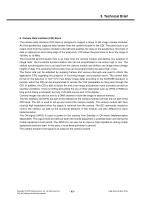
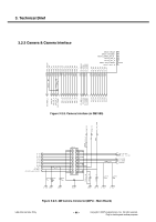
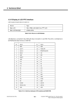
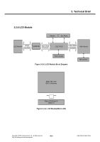
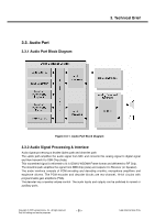
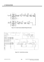
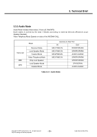
3. Technical Brief 3.2.5 Display & LCD FPC Interface LCD module include device in table 3-2 Device Main LCD Main LCD Backlight Type 320 x RGB x 240 262K Color TFT LCD 4 White LEDs Table 3-2-3. Device in LCD Module LCD Module is connected to Key PCB with 40-pin Connector in sub PCB. The LCD is controlled by 8bit PDI(Parallel Data Interface) in DB3100. No. Signal 1 GND 2 LED C1 3 LED C4 4 LED A 5 GND 6 RESET 7 GND 8 D15 9 D13 10 D11 11 D9 12 D7 13 D5 14 D3 15 D1 16 RD/ 17 RS 18 VSYNC 19 IOVCC(1.8V) 20 GND No. Signal 21 GND 22 VDD(2.8V) 23 MAKER ID(LOW) 24 CS/ 25 WR/ 26 D0 27 D2 28 D4 29 D6 30 D8 31 D10 32 D12 33 D14 34 GND 35 GND 36 IF(IM) 37 GND 38 LED C3 39 LED C2 40 GND Table 3-2-4. Interface between LCD module and SUB PCB LGE Internal Use Only - 48 - Copyright © 2007 LG Electronics. Inc. All right reserved. Only for training and service purposes
-
 1
1 -
2
-
3
-
4
-
5
-
6
-
7
-
8
-
9
-
10
-
11
-
12
-
13
-
14
-
15
-
16
-
17
-
18
-
19
-
20
-
21
-
22
-
23
-
24
-
25
-
26
-
27
-
28
-
29
-
30
-
31
-
32
-
33
-
34
-
35
-
36
-
37
-
38
-
39
-
40
-
41
-
 42
42 -
 43
43 -
 44
44 -
 45
45 -
 46
46 -
 47
47 -
 48
48 -
 49
49 -
 50
50 -
 51
51 -
 52
52 -
53
-
54
-
55
-
56
-
57
-
58
-
59
-
60
-
61
-
62
-
63
-
64
-
65
-
66
-
67
-
68
-
69
-
70
-
71
-
72
-
73
-
74
-
75
-
76
-
77
-
78
-
79
-
80
-
81
-
82
-
83
-
84
-
85
-
86
-
87
-
88
-
89
-
90
-
91
-
92
-
93
-
94
-
95
-
96
-
97
-
98
-
99
-
100
-
101
-
102
-
103
-
104
-
105
-
106
-
107
-
108
-
109
-
110
-
111
-
112
-
113
-
114
-
115
-
116
-
117
-
118
-
119
-
120
-
121
-
122
-
123
-
124
-
125
-
126
-
127
-
128
-
129
-
130
-
131
-
132
-
133
-
134
-
135
-
136
-
137
-
138
-
139
-
140
-
141
-
142
-
143
-
144
-
145
-
146
-
147
-
148
-
149
-
150
-
151
-
152
-
153
-
154
-
155
-
156
-
157
-
158
-
159
-
160
-
161
-
162
-
163
-
164
-
165
-
166
-
167
-
168
-
169
-
170
-
171
-
172
-
173
-
174
-
175
-
176
-
177
-
178
-
179
-
180
-
181
-
182
-
183
-
184
-
185
-
186
-
187
-
188
-
189
-
190
-
191
-
192
-
193
-
194
-
195
-
196
-
197
-
198
-
199
-
200
-
201
-
202
-
203
-
204
-
205
-
206
-
207
-
208
-
209
 |
 |