LG KU580 Service Manual - Page 72
A. Transmitter Part, B. Receiver part
 |
View all LG KU580 manuals
Add to My Manuals
Save this manual to your list of manuals |
Page 72 highlights
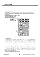
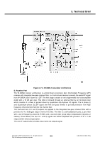
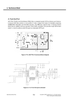
3. Technical Brief A. Transmitter Part Polar modulation transmitter architecture based on the direct phase/frequency modulation/synthesizer architecture is implemented for GSM, GPRS and EDGE. This architecture has the capability of generating both the GSM/GPRS constant envelope GMSK modulation and the linear EDGE 8-PSK modulation in a very cost efficient way. The motivation for a polar modulation transmitter architecture compared to traditionally linear architectures is to reduce the output noise (thus eliminating the need for off-chip filters) reduce the power consumption by utilizing non-linear switching analog signal processing blocks, and to eliminate the need for an RF isolator. The transmitter block consists of several sub-blocks: A separate block is used to convert the digital bit streams from the baseband into parallel words to be used in the DACs and the Sigma Delta modulator. The combined DAC and LP-filter is used to convert the digital words of the digital block into analog signals. The second FM-path is used to add the high frequency part of the FM to the VCO. It also includes an auto-tuning block that compensates VCO gain variations. In the Sigma Delta modulator block, the phase/frequency modulator in this polar modulation architecture is a sigma-delta controlled fractional-N frequency synthesizer with an additional frequency insertion point after the loop filter at the input of the VCO. In addition, The TX-buffer is used to drive the PA with the correct power level. A divide by 2 or 4 block is used to generate the correct output frequency from the 4 GHz VCO. The phase locked loop has two information inputs: the divider ratio in the feedback path and a direct path to the VCO. The phase locked loop generates the radio frequency carrier including the phase modulation information at the desired channel frequency. B. Receiver part Direct down-conversion zero-IF receiver architecture is used for the four EDGE/GSM/GPRS frequency bands 800, 900, 1800 and 1900 MHz. The complete receiver with four Low Noise Amplifiers (LNAs), one for each supported band, is integrated on chip. After the down-conversion, the in-phase and quadrature-phase components are low pass filtered with two anti-alias filters before the signals are fed to the integrated high dynamic range sigma-delta A/D-converters. The only required external components are the band selectivity SAW filters in front of the LNAs. One filter is required per supported frequency band. The digital output signals are sent over a serial interface to the digital baseband circuit for further processing and detection. Copyright © 2007 LG Electronics. Inc. All right reserved. Only for training and service purposes - 73 - LGE Internal Use Only
-
 1
1 -
2
-
3
-
4
-
5
-
6
-
7
-
8
-
9
-
10
-
11
-
12
-
13
-
14
-
15
-
16
-
17
-
18
-
19
-
20
-
21
-
22
-
23
-
24
-
25
-
26
-
27
-
28
-
29
-
30
-
31
-
32
-
33
-
34
-
35
-
36
-
37
-
38
-
39
-
40
-
41
-
42
-
43
-
44
-
45
-
46
-
47
-
48
-
49
-
50
-
51
-
52
-
53
-
54
-
55
-
56
-
57
-
58
-
59
-
60
-
61
-
62
-
63
-
64
-
65
-
66
-
 67
67 -
 68
68 -
 69
69 -
 70
70 -
 71
71 -
 72
72 -
 73
73 -
 74
74 -
 75
75 -
 76
76 -
 77
77 -
78
-
79
-
80
-
81
-
82
-
83
-
84
-
85
-
86
-
87
-
88
-
89
-
90
-
91
-
92
-
93
-
94
-
95
-
96
-
97
-
98
-
99
-
100
-
101
-
102
-
103
-
104
-
105
-
106
-
107
-
108
-
109
-
110
-
111
-
112
-
113
-
114
-
115
-
116
-
117
-
118
-
119
-
120
-
121
-
122
-
123
-
124
-
125
-
126
-
127
-
128
-
129
-
130
-
131
-
132
-
133
-
134
-
135
-
136
-
137
-
138
-
139
-
140
-
141
-
142
-
143
-
144
-
145
-
146
-
147
-
148
-
149
-
150
-
151
-
152
-
153
-
154
-
155
-
156
-
157
-
158
-
159
-
160
-
161
-
162
-
163
-
164
-
165
-
166
-
167
-
168
-
169
-
170
-
171
-
172
-
173
-
174
-
175
-
176
-
177
-
178
-
179
-
180
-
181
-
182
-
183
-
184
-
185
-
186
-
187
-
188
-
189
-
190
-
191
-
192
-
193
-
194
-
195
-
196
-
197
-
198
-
199
-
200
-
201
-
202
-
203
-
204
-
205
-
206
-
207
-
208
-
209
 |
 |