LG KU950 Service Manual - Page 134
Vibrator trouble
 |
View all LG KU950 manuals
Add to My Manuals
Save this manual to your list of manuals |
Page 134 highlights
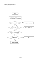
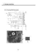
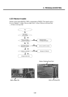
4. TROUBLE SHOOTING 4.20 Vibrator trouble Vibrator control signal (MOTOR_PWR-) is generated by PM6650. That signal's path is : Pin 25 of PM6650 → CN801 PIN 36 of Main PCB → CN101 PIN 36 of LCD Sub PCB → TP103 of LCD Sub PCB Start The vibrator Donít working? YES Vibrator Solderling NO and vibrator itself OK? YES Is the LCD Wire Connector NO appropriately Connected? YES NO Change the LCD Sub PCB YES Change the Main PCB Resolder Vibrator Or Change the Vibrator Connect LCD Wire Connetor Change the LCD Module Vibrator Soldering Check Point 1 CN801 of Main PCB 40 CN101 of LCD Sub PCB - 135 -
-
 1
1 -
2
-
3
-
4
-
5
-
6
-
7
-
8
-
9
-
10
-
11
-
12
-
13
-
14
-
15
-
16
-
17
-
18
-
19
-
20
-
21
-
22
-
23
-
24
-
25
-
26
-
27
-
28
-
29
-
30
-
31
-
32
-
33
-
34
-
35
-
36
-
37
-
38
-
39
-
40
-
41
-
42
-
43
-
44
-
45
-
46
-
47
-
48
-
49
-
50
-
51
-
52
-
53
-
54
-
55
-
56
-
57
-
58
-
59
-
60
-
61
-
62
-
63
-
64
-
65
-
66
-
67
-
68
-
69
-
70
-
71
-
72
-
73
-
74
-
75
-
76
-
77
-
78
-
79
-
80
-
81
-
82
-
83
-
84
-
85
-
86
-
87
-
88
-
89
-
90
-
91
-
92
-
93
-
94
-
95
-
96
-
97
-
98
-
99
-
100
-
101
-
102
-
103
-
104
-
105
-
106
-
107
-
108
-
109
-
110
-
111
-
112
-
113
-
114
-
115
-
116
-
117
-
118
-
119
-
120
-
121
-
122
-
123
-
124
-
125
-
126
-
127
-
128
-
 129
129 -
 130
130 -
 131
131 -
 132
132 -
 133
133 -
 134
134 -
 135
135 -
 136
136 -
 137
137 -
 138
138 -
 139
139 -
140
-
141
-
142
-
143
-
144
-
145
-
146
-
147
-
148
-
149
-
150
-
151
-
152
-
153
-
154
-
155
-
156
-
157
-
158
-
159
-
160
-
161
-
162
-
163
-
164
-
165
-
166
-
167
-
168
-
169
-
170
-
171
-
172
-
173
-
174
-
175
-
176
-
177
-
178
-
179
-
180
-
181
-
182
-
183
-
184
-
185
-
186
-
187
-
188
-
189
-
190
-
191
-
192
-
193
-
194
-
195
-
196
-
197
-
198
-
199
-
200
-
201
-
202
-
203
-
204
-
205
-
206
-
207
-
208
-
209
-
210
-
211
-
212
-
213
-
214
-
215
-
216
-
217
-
218
-
219
-
220
-
221
 |
 |
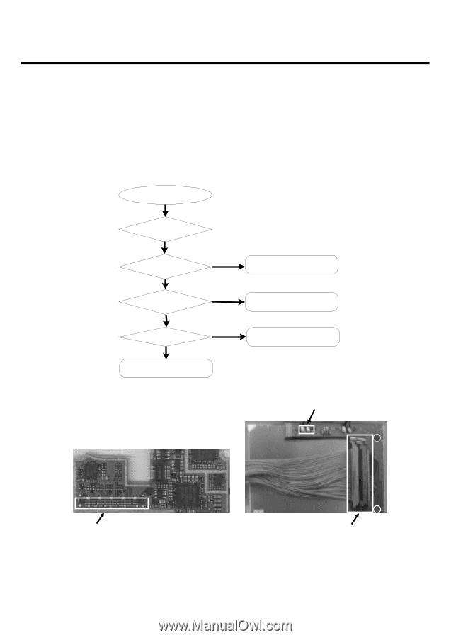
4. TROUBLE SHOOTING
- 135 -
4.20 Vibrator trouble
Vibrator control signal (MOTOR_PWR-) is generated by PM6650. That signal’s path is :
Pin 25 of PM6650
→
CN801 PIN 36 of Main PCB
→
CN101 PIN 36 of LCD Sub PCB
→
TP103 of LCD Sub PCB
Start
Change the Main PCB
Connect LCD Wire Connetor
YES
YES
YES
NO
NO
The vibrator
Donít working?
YES
Change the LCD Sub PCB
Change the LCD Module
Resolder Vibrator
Or Change the Vibrator
Vibrator Solderling
and vibrator itself OK?
NO
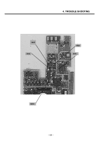
CN101 of LCD Sub PCB
CN801 of Main PCB
Vibrator
Soldering Check Point
1
40
Is the LCD Wire Connector
appropriately Connected?