LG LGKS20 Operating Instructions - Page 37
SubsystemMSM7200
 |
View all LG LGKS20 manuals
Add to My Manuals
Save this manual to your list of manuals |
Page 37 highlights
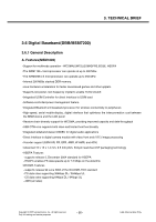
3. TECHNICAL BRIEF 3.8. Subsystem(MSM7200) 3.8.1. ARM Microprocessor Subsystem The MSM7200 device uses an embedded ARM1136-J, ARM926EJ-S microprocessor. This microprocessor, through the system software, controls most of the functionality for the MSM, including control of the external peripherals such as the keypad, LCD, SDRAM, and NANDFlash devices. Through a QUALCOMM proprietary serial bus interface (SBI) the ARM926EJ-S configures and controls the functionality of the RTR6275 and PM7540 devices.. 3.8.2. UMTS Subsystem The UMTS Subsystem performs the digital UMTS signal processing. Its components include: • Searcher engine • Demodulating fingers • Combining block • Frame deinterleaver • Viterbi decoder • Up-link subsystem • Turbo decoder On the down-link channel the UMTS subsystem searches, demodulates, and decodes incoming CPICH, CCPCH, SCH, and Traffic Channel information. It extracts packet data from the downlink traffic channel and prepares the packet data for processing. For the up-link, the WCDMA subsystem processes the packet data and modulates the up-link traffic channel (DCH). 3.8.3. GSM Subsystem The GSM/GPRS/EGPRS subsystem reuses the MSM6280 GSM core. It performs the digital GSM signal processing and PA gain controls for GPRS support. The PA output level is controlled by an analog signal generated on the MSM. In GSM mode, the power profile ramps up before the burst and ramps down after the burst. In GPRS mode, at the beginning of each burst (up to four active transmit slots), PA must be smoothly ramped up to some desired output power level, held at that level for the current slot, smoothly ramped down/up during the transition period and held to the new level for the next slot until the last slot. Then it must be smoothly ramped down to near-zero level. The MSM6275 support differential GSM PA power control output. The RF interface communicates with the mobile station external RF circuits. Signals to these circuits control signal gain in the Rx and Tx signal path, control DC offset errors, and maintain the system frequency reference. 3.8.4. RF Interface The RF interface communicates with the mobile station's external RF and analog baseband circuits. Signals to these circuits control signal gain in the Rx and Tx signal path and maintain The system's frequency reference. Copyright © 2007 LG Electronics. Inc. All right reserved. Only for training and service purposes - 39 - LGE Internal Use Only
-
 1
1 -
2
-
3
-
4
-
5
-
6
-
7
-
8
-
9
-
10
-
11
-
12
-
13
-
14
-
15
-
16
-
17
-
18
-
19
-
20
-
21
-
22
-
23
-
24
-
25
-
26
-
27
-
28
-
29
-
30
-
31
-
 32
32 -
 33
33 -
 34
34 -
 35
35 -
 36
36 -
 37
37 -
 38
38 -
 39
39 -
 40
40 -
 41
41 -
 42
42 -
43
-
44
-
45
-
46
-
47
-
48
-
49
-
50
-
51
-
52
-
53
-
54
-
55
-
56
-
57
-
58
-
59
-
60
-
61
-
62
-
63
-
64
-
65
-
66
-
67
-
68
-
69
-
70
-
71
-
72
-
73
-
74
-
75
-
76
-
77
-
78
-
79
-
80
-
81
-
82
-
83
-
84
-
85
-
86
-
87
-
88
-
89
-
90
-
91
-
92
-
93
-
94
-
95
-
96
-
97
-
98
-
99
-
100
-
101
-
102
-
103
-
104
-
105
-
106
-
107
-
108
-
109
-
110
-
111
-
112
-
113
-
114
-
115
-
116
-
117
-
118
-
119
-
120
-
121
-
122
-
123
-
124
-
125
-
126
-
127
-
128
-
129
-
130
-
131
-
132
-
133
-
134
-
135
-
136
-
137
-
138
-
139
-
140
-
141
-
142
-
143
-
144
-
145
-
146
-
147
-
148
-
149
-
150
-
151
-
152
-
153
-
154
-
155
-
156
-
157
-
158
-
159
-
160
-
161
-
162
-
163
-
164
-
165
-
166
-
167
-
168
-
169
-
170
-
171
-
172
-
173
-
174
-
175
-
176
-
177
-
178
-
179
-
180
-
181
-
182
-
183
-
184
-
185
-
186
-
187
-
188
-
189
-
190
-
191
-
192
-
193
-
194
-
195
-
196
-
197
-
198
-
199
-
200
-
201
-
202
-
203
-
204
-
205
-
206
-
207
-
208
-
209
 |
 |