LG LP090CED1 Service Manual - Page 22
Wall Sleeve Installation
 |
View all LG LP090CED1 manuals
Add to My Manuals
Save this manual to your list of manuals |
Page 22 highlights
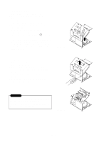
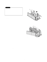
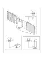
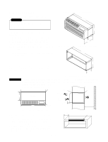
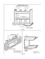
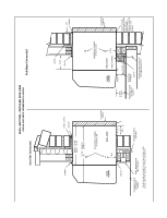
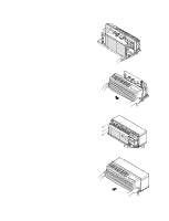
3.2 WALL SLEEVE INSTALLATION 3.2.1 Wall Case Installation Data General Generally, units are installed 3" to 5" above the floor (flush to finished floor installation is possible) as near to the center of the room as possible; underneath a window or a glass panel is typical. Normal installation of the wall case allows installation flexibility; from flush with the finished interior wall to a minimum of 1/4" of the wall case extending beyond the finished exterior of the building. Special consideration must be given to installations where the wall case does not extend a minimum of 1/4" beyond the finished exterior wall. framing, moving electrical outlets, and other expensive modifications. For existing construction it is important that carpentry, masonry and electrical work be performed by competent, qualified personnel. Since installations in existing construction may involve removal of building material from the structure, locating the wall case must be done correctly. Regardless of the installation, there are several things to consider when selecting a location for installing the unit. For instance, drapery location could interfere with air discharge, and placement of furniture may have an impact on the performance of the unit. The following information is intended to minimize installation problems and assure you of trouble-free installation. Refer to page 24 for required wall opening dimensions. Minimum recommended interior and exterior case projection for standard wall thicknesses are shown in the drawings in this manual. The case may be installed flush with the finished indoor wall. Mounting an outdoor grille or louver section to the building face may cause a space between the outdoor coil and the louver section. Air splitters, aligned with the ends of the outdoor coil, must be installed between the outdoor coil inlet and outlet air streams. Gaps between the outdoor coil and the louver section may allow condenser air recirculation and affect the operation of the unit. See page 40 for requirements for custom louver sections. The wall case should be level from side to side and from level to 1/4 bubble tilt to the outdoors. The condensate disposal system in the unit is designed to dissipate the condensate water generated during cooling operation in accordance with ARI standards and actually uses this water for maximum unit efficiency. A level unit will also insure proper performance of the Internal Condensate Removal (ICR) system optional on heat pump units. For new construction, early planning with the architect is necessary. Unit location, electrical connection locations, and wall openings of the proper dimensions are essential to avoid the necessity of rework, fillers, -22-
-
 1
1 -
2
-
3
-
4
-
5
-
6
-
7
-
8
-
9
-
10
-
11
-
12
-
13
-
14
-
15
-
16
-
 17
17 -
 18
18 -
 19
19 -
 20
20 -
 21
21 -
 22
22 -
 23
23 -
 24
24 -
 25
25 -
 26
26 -
 27
27 -
28
-
29
-
30
-
31
-
32
-
33
-
34
-
35
-
36
-
37
-
38
-
39
-
40
-
41
-
42
-
43
-
44
-
45
-
46
-
47
-
48
-
49
-
50
-
51
-
52
-
53
-
54
-
55
-
56
-
57
-
58
-
59
 |
 |
