LG LP090CED1 Service Manual - Page 39
Fuse Holder Kit
 |
View all LG LP090CED1 manuals
Add to My Manuals
Save this manual to your list of manuals |
Page 39 highlights
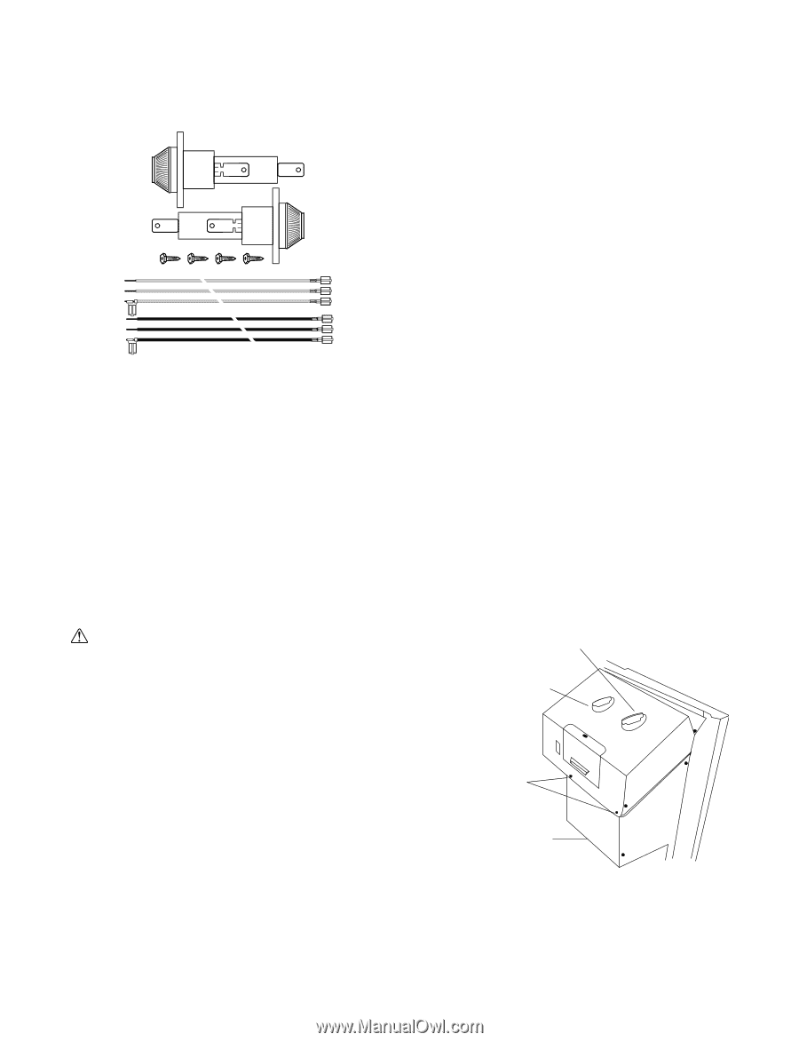
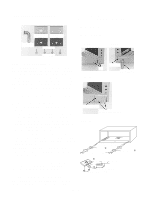
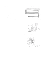
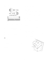
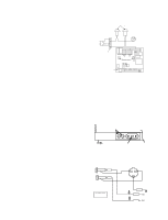
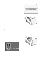
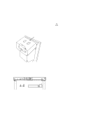
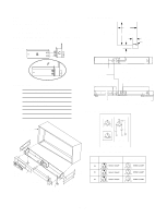
Fuse Holder Kit Part No: AYFH1101 CAUTION Use Copper Conductors Only! Unit terminals are not designed to accept other types of conductors. Failure to use copper conductors may result in equipment damage. Important Note: All wiring must comply with applicable local and national codes. Type and location of fused disconnect switch(es) must comply with all applicable codes. Failure to follow these codes could result in overheating and equipment failure. Description This optional fuse holder kit can be installed directly in the chassis or in the optional subbase. Fuse holder kits are available in 230/ 208 volt ratings. The installer should supply time delay fuses at 15, 20, 25, or 30 amps in accordance with the Maximum Overcurrent Protection as listed on the unit nameplate. Fuses may be purchased from the parts department. Note: The installation and servicing of this equipment must be performed by qualified, experienced technicians only. WARNING Hazardous Voltage! Disconnect all electric power, including remote disconnects before servicing. Follow proper lockout/ tagout procedures to ensure the power can not be inadvertently energized. Failure to disconnect power before servicing could result in death or serious injury. Important Note: The unit OFF switch does not disconnect all electrical power to this unit. Receiving Upon receipt of the product, inspect the shipping carton for signs of visible damage. Report any damage or shortage to the carrier and note it on the delivery receipt. Unit must be stored in its original shipping carton in a dry, secure place prior to its installation and use. Installation The installation and servicing of the equipment referred to in this booklet should be performed by qualified, experienced technicians. Fuse Holder Kit Installation (Without Subbase) 1. Remove front by rotating bottom outward and then lifting up and out from chassis. Figure 50 - Control Panel Mode Switch Thermostat Remove two screws to gain access inside Control Panel Fuse Holder Knockouts under panel -39-
-
 1
1 -
2
-
3
-
4
-
5
-
6
-
7
-
8
-
9
-
10
-
11
-
12
-
13
-
14
-
15
-
16
-
17
-
18
-
19
-
20
-
21
-
22
-
23
-
24
-
25
-
26
-
27
-
28
-
29
-
30
-
31
-
32
-
33
-
 34
34 -
 35
35 -
 36
36 -
 37
37 -
 38
38 -
 39
39 -
 40
40 -
 41
41 -
 42
42 -
 43
43 -
 44
44 -
45
-
46
-
47
-
48
-
49
-
50
-
51
-
52
-
53
-
54
-
55
-
56
-
57
-
58
-
59
 |
 |