LG WKGX201HWA Owners Manual - Page 18
Installing the Dryer Side, Vent Kit
 |
View all LG WKGX201HWA manuals
Add to My Manuals
Save this manual to your list of manuals |
Page 18 highlights
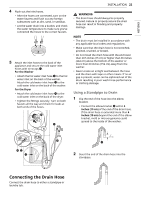
18 INSTALLATION a Terminal block b UL-listed strain relief c UL-listed 3-wire power cord 5 Attach the two hot leads (black and red) of the power cord to the outer terminal block screws. 6 Attach the neutral (white) wire to the center terminal block screw. 7 Connect the external ground (if required by local codes) to the green ground screw. 8 Tighten all screws securely. 9 Reinstall the terminal block access cover. WARNING • Use long-sleeved gloves and safety glasses. • Use a heavy metal vent. • Do not use plastic or thin foil ducts. • Clean old ducts before installing the appliance. NOTE • An adapter kit, part number 383EEL9001B, may be purchased from your LG retailer. This kit contains duct components necessary to change the appliance vent location. • Right-side venting is not available on gas models. • Bottom venting is not available on stacked or integrated stacked models. Side Venting 1 Remove the rear exhust duct retaining screw a and pull out the exhaust duct b. a b a Hot lead (black and red) b Neutral wire (white) c External ground wire (if required by local codes) d Wire from the appliance harness e Ground screw (green) Installing the Dryer Side Vent Kit The appliance is configured to vent to the rear. It can also vent to the side. 2 Press the tabs on the knockout c and carefully remove the knockout for the desired vent opening. (Right-side venting is not available on gas models.) Press the adapter duct d onto the blower housing and secure to the base of the dryer as shown. d c 3 Preassemble a 4" (10 cm) elbow e to the next 4" (10 cm) duct section, and secure all joints with duct tape. Be sure that the male end of the elbow faces AWAY from the dryer. Insert the elbow/duct assembly through the side opening and press it onto the adapter duct. Secure it in place with duct tape. Be sure that
-
 1
1 -
2
-
3
-
4
-
5
-
6
-
7
-
8
-
9
-
10
-
11
-
12
-
 13
13 -
 14
14 -
 15
15 -
 16
16 -
 17
17 -
 18
18 -
 19
19 -
 20
20 -
 21
21 -
 22
22 -
 23
23 -
24
-
25
-
26
-
27
-
28
-
29
-
30
-
31
-
32
-
33
-
34
-
35
-
36
-
37
-
38
-
39
-
40
-
41
-
42
-
43
-
44
-
45
-
46
-
47
-
48
-
49
-
50
-
51
-
52
-
53
-
54
-
55
-
56
-
57
-
58
-
59
-
60
-
61
-
62
-
63
-
64
-
65
-
66
-
67
-
68
-
69
-
70
-
71
-
72
-
73
-
74
-
75
-
76
-
77
-
78
-
79
-
80
-
81
-
82
-
83
-
84
-
85
-
86
-
87
-
88
-
89
-
90
-
91
-
92
-
93
-
94
-
95
-
96
-
97
-
98
-
99
-
100
-
101
-
102
-
103
-
104
-
105
-
106
-
107
-
108
-
109
-
110
-
111
-
112
-
113
-
114
-
115
-
116
-
117
-
118
-
119
-
120
-
121
-
122
-
123
-
124
-
125
-
126
-
127
-
128
-
129
-
130
-
131
-
132
-
133
-
134
-
135
-
136
-
137
-
138
-
139
-
140
-
141
-
142
-
143
-
144
-
145
-
146
-
147
-
148
-
149
-
150
-
151
-
152
-
153
-
154
-
155
-
156
-
157
-
158
-
159
-
160
-
161
-
162
-
163
-
164
-
165
-
166
-
167
-
168
-
169
-
170
-
171
-
172
-
173
-
174
-
175
-
176
-
177
-
178
-
179
-
180
-
181
-
182
-
183
-
184
-
185
-
186
-
187
-
188
-
189
-
190
-
191
-
192
-
193
-
194
-
195
 |
 |
