Lasko T42951 User Manual - Page 2
Caution - manual
 |
View all Lasko T42951 manuals
Add to My Manuals
Save this manual to your list of manuals |
Page 2 highlights
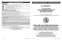
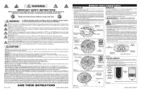
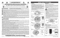
WARNING IMPORTANT SAFETY INSTRUCTIONS When using electrical appliances, these instructions and warnings should always be followed to reduce the risk of fire, electrical shock and injury to persons: Read all instructions before using this Fan. WARNING TO REDUCE THE RISK OF FIRE, ELECTRICAL SHOCK OR PERSONAL INJURY, ALWAYS FOLLOW THESE IMPORTANT SAFETY INSTRUCTIONS AND WARNINGS: DO NOT use this Fan to ventilate areas where flammable liquids or vapors are used, stored or are present, including paints, gasoline, varnishes, floor refinishing products or solvents. ALWAYS read and follow all warnings and instructions on the containers for these products! ALWAYS be sure the plug fits tightly into the outlet. When plugs fit loosely into outlets, they may slip partially out of the outlet and create a poor connection. This may cause outlets to overheat and create a potential fire hazard. Outlets in this condition should be replaced by a qualified electrician. ALWAYS unplug the power cord when servicing, cleaning or moving the Fan. DO NOT use the ON/OFF switch as the sole means of disconnecting power. NEVER leave children unattended when the Fan is on or plugged in. ALWAYS turn off and unplug the Fan when not in use. BE CERTAIN that the power source for the Fan is 120V AC. DO NOT plug the Fan into 240V or other power source. The Blue Plug™ on your Lasko Fan is a safety feature. It contains a non-replaceable safety device (fuse) that should not be removed or tampered with. To reduce the risk of fire, electric shock and personal injury, DO NOT attempt to remove, replace, repair or tamper with the originally supplied plug. If the Fan has stopped functioning, it may be due to the safety device incorporated in this plug. THIS FAN HAS A POLARIZED PLUG (one blade is wider than the other). This plug is designed to fit into the outlet only one way. Match the wide blade to wide slot in outlet and FULLY INSERT. DO NOT attempt to bypass or defeat this safety feature. If the plug does not fit in the outlet, consult a qualified electrician. The outlet may need to be replaced. CAUTION • AVOID the use of extension cords, power strips, power taps, outlet style air fresheners or other cord connected device, as these devices may overheat and cause a fire hazard. • DO NOT route power cord under rugs, carpets, runners or furniture. This may damage the cord or cause it to overheat creating a fire hazard. • ALWAYS place the Fan on a stable, flat, level surface while in operation to prevent the Fan from overturning. • NEVER insert or allow fingers or objects to enter grill openings while Fan is in operation or injury and/or damage to the Fan may occur. • DO NOT block, cover or obstruct air flow to or from the Fan while in operation. • DO NOT use this Fan outdoors or near water or wet locations such as a bath tub, pool or hot tub. Use of this Fan in a wet location may create a shock hazard. • DO NOT run cord under carpeting. Do not cover cord with throw rugs, runners, or similar coverings. Do not route cord under furniture or appliances. Arrange cord away from traffic area and where it will not be tripped over. • NEVER use a single extension cord to operate more than one Fan or other electrical device. • DO NOT use this Fan if it has been damaged or is not functioning properly. • Remote controls for other appliances or electronic equipment can sometimes interfere with the operation of this Fan. If this occurs, move the Fan to another location. • Keep Fan remote control unit away from chairs and your bed where it may be sat or laid upon and inadvertently turn on the Fan. • THIS FAN DOES NOT MEET THE REQUIREMENTS OF NEC ARTICLE 547-7 (2008).This Fan is not suitable for use in agricultural facil- ities including areas where livestock, poultry or other animals are confined. Please refer to National Electric Code (NEC) Article 547-7 (2008), or applicable state or local codes or standards relating to electrical requirements for agricultural buildings. • THIS FAN DOES NOT MEET THE REQUIREMENTS OF NEC ARTICLE 500 (2008).This Fan is not suitable for use in hazardous locations. Please refer to National Electric Code (NEC) Article 500 or applicable state or local codes or standards relating to electrical requirements for hazardous locations. NOTICE: This equipment has been tested and found to comply with the limits for a Class B digital device, pursuant to Part 15 of the FCC Rules. These limits are designed to provide reasonable protection against harmful interference in a residential installation. This equipment generates uses and can radiate radio frequency energy and, if not installed and used in accordance with the instructions, may cause harmful interference to radio communications. However, there is no guarantee that interference will not occur in a particular installation. If this equipment does cause harmful interference to radio or television reception, which can be determined by turning the equipment off and on, the user is encouraged to try to correct the interference by one or more of the following measures: Reorient or relocate the receiving antenna. Increase the separation between the equipment and receiver. Connect the equipment into an outlet on a circuit different from that to which the receiver is connected. Consult the dealer or an experienced radio/TV technician for help. The user is cautioned that changes and modifications made to the equipment without the approval of manufacturer could void the user's authority to operate this equipment. SAVE THESE INSTRUCTIONS Rev. A 12/18 2 T42951/T42952/T42954ES MODELOS T42951/T42952/T42954 ENSAMBLAJE 1. Para fácil ensamblado, apoye el ventilador de modo tal que la parrilla frontal y el panel de control apunten hacia arriba. 2. Ensamble las mitades de la base de apoyo al interconectar las Protuberancias en la Base de Apoyo B en las Ranuras de la Protuberancia en la Bbase de Apoyo A. (Figura 1) 3. Alinee la Montura de la Base de apoyo con la Base del Motor. Introduzca el cable eléctrico a través del orificio grande en el centro de la montura de la base de apoyo. Asegúrese de alinear las Ranuras de los Ganchos (Figura 1) en la Montura de la Base de apoyo con los Ganchos en la Base del Motor. La flecha de alineación en la montura de la base de apoyo debe estar alineada con la flecha de alineación en la Base del Motor (Figura 2 y Figura 2A). 4. Para fijar la Montura de la Base de apoyo a la Base del Motor, sostenga la base del motor en su lugar mientras gira la Montura de la Base de apoyo en el sentido de las agujas del reloj (hacia el símbolo de bloqueado) hasta que deje de girar y encaje en su lugar. (Figura 3 y Figura 3A). 5. Suavemente elimine cualquier sobrante del Cable Eléctrico y colóquelo en el Orificio de Colocación del Cable. (Figura 4) Base de Soporte B Base de Soporte A Ranuras de Protuberancias Ranuras de Ganchos Copas Figura 1 Conjunto de la Base de Soporte OPERACIÓN Puede operar este ventilador con los controles manuales ubicados en la parte superior de la unidad (Figuras 5) o con el control remoto (Figuras 6). 1. Coloque el ventilador sobre una superficie firme y nivelada. ADVERTENCIA: Los tacos de plástico o hule, tales como las patas de esta unidad, pueden pegarse a la superficie de los muebles. La unidad podría dejar un residuo capaz de oscurecer, manchar o dejar marcas permanentes en el acabado de ciertas superficies de muebles, incluyendo superficies y pisos de madera. 2. Conecte el cable eléctrico a un tomacorriente de 120 volts. Asegúrese que el enchufe encaje firmemente en el tomacorriente. Asegúrese que el enchufe encaje firmemente en el tomacorriente. De no encajar firmemente en el tomacorriente, podrían deslizarse parcial o completamente fuera del tomacorriente apenas con un ligero movimiento del cable conectado. Los receptáculos en esta condición pueden sobrecalentarse y constituir un grave riesgo de incendio; si está cubierto por una cortina, el peligro de incendio es aún mayor. 3. Suministre corriente eléctrica al ventilador al presionar el Botón de Encendido ( ). El ventilador operará inicialmente en velocidad alta, velocidad 3. 4. VELOCIDAD DEL VENTILADOR: Ahora puede ajustar la velocidad del ventilador al nivel deseado - 1 (baja), 2 (mediana) ó 3 (alta) - pulsando el Botón Velocidad ( ). 5. OSCILACIÓN: Presione el Botón de Oscilación ( ) para iniciar y detener la función de oscilación. 6. FUNCIÓN DE TEMPORIZADOR: La función temporizadora permite ajustar la unidad para que funcione durante un lapso que va desde 1/2 hora hasta 7 1/2 horas, en incrementos de 1/2 hora. Continúe pulsando el Botón del Temporizador ( ) para llegar a la configuración de tiempo deseada. Para cancelar el temporizador, pulse el Botón de Temporizador ( ) hasta que las luces se apaguen. 7. CARACTERÍSTICA DE NOCHE: Presione el Botón de Noche ( ) una vez para activar la función. Las luces del ventilador se atenuarán un 50 %. El ventilador funcionará en la configuración alta (3) por una hora, cambiará a la configuración media (2) por una hora y, por último, cambiará a la configuración baja (1) hasta que el usuario interactúe con el ventilador. La funcion de noche no funciona con ninguna otra funcion, exepto oscilacion. Presione Cualquier otro boton para cancelar la funcion de noche. 8. Después de apagar el ventilador, desconecte la unidad del tomacorriente eléctrico. Ganchos Cable Eléctrico Figura 2 Base del Motor Cable Eléctrico Figura 3 Figura 2A Base del Motor Figura 3A Conjunto de la Base de Soporte Orificio de Colocación del Cable Cable Eléctrico Botón Temporizador Botón de Noche Botón de Oscilación Botón de Velocidad Botón Alimentación Figura 3 CONTROL REMOTO 1. Instale las dos baterías "AAA" (no incluídas), como se muestra en la Figura 6. 2. Todas las funciones realizadas con el Control Remoto pueden realizarse de igual forma con los Controles Manuales. 3. No mezcle baterías viejas y nuevas. No mezcle baterías alcalinas, estándar (carbono-cinc) o recargables (níquel-cadmio). 4. NO ARROJE LAS BATERÍAS AL FUEGO, LAS BATERÍAS PUEDEN ESTALLAR O PUEDE DERRAMARSE EL LÍQUIDO CONTENIDO. Botón Alimentación Botón Velocidad Oscilación Botón Botón Temporizador PPOOWWEERR SSPPEEEEDD OOSSCC TTIIMMEERR LNOIGUVHETRS Baterías AAA Botón de Noche Figura 4 Mantenga las baterías fuera del alcance de los niños Figura 4 Rev. A 12/18 7 T42951/T42952/T42954ES
-
 1
1 -
 2
2 -
 3
3 -
 4
4
 |
 |
