Lenovo B570e Hardware Maintenance Manual
Lenovo B570e Manual
 |
View all Lenovo B570e manuals
Add to My Manuals
Save this manual to your list of manuals |
Lenovo B570e manual content summary:
- Lenovo B570e | Hardware Maintenance Manual - Page 1
Hardware Maintenance Manual Lenovo V570, B570, and B570e - Lenovo B570e | Hardware Maintenance Manual - Page 2
and the product it supports, be sure to read the general information under Appendix A "Notices" on page 87. Second Edition (January 2012) © Copyright Lenovo 2012. LIMITED AND RESTRICTED RIGHTS NOTICE: If data or software is delivered pursuant a General Services Administration "GSA" contract, use - Lenovo B570e | Hardware Maintenance Manual - Page 3
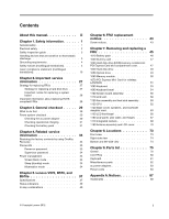
34 Screen blank mode 34 Sleep (standby) mode 34 Hibernation mode 34 Chapter 5. Lenovo V570, B570, and B570e 37 Specifications 37 Status indicators 39 Fn key combinations 40 Chapter 6. FRU replacement notices 43 Screw notices 43 Chapter 7. Removing and replacing a FRU 45 1010 Battery pack - Lenovo B570e | Hardware Maintenance Manual - Page 4
ii Hardware Maintenance Manual - Lenovo B570e | Hardware Maintenance Manual - Page 5
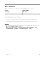
About this manual This manual contains service and reference information for the following Lenovo® products. Product Lenovo V570 Lenovo B570 Lenovo B570e Machine type (MT) 1066, 20092 1068, 20093 5215, 20173 Use this manual to troubleshoot problems. The manual is divided into the following - Lenovo B570e | Hardware Maintenance Manual - Page 6
iv Hardware Maintenance Manual - Lenovo B570e | Hardware Maintenance Manual - Page 7
service a Lenovo Notebook. • "General safety" on page 1 • "Electrical safety" on page 2 • "Safety inspection guide • Before you start the machine, make sure that other service technicians and the are servicing the machine. • Keep your toolcase away from walk areas so that other people will not - Lenovo B570e | Hardware Maintenance Manual - Page 8
supplies - Removing or installing main units • Before you start to work on the machine, unplug the power cord you work with very high voltages; Instructions for these precautions are in the cause personal injury and machine damage. • Do not service the following parts with the power on when they Manual - Lenovo B570e | Hardware Maintenance Manual - Page 9
to protect users and service technicians from injury. This guide addresses only those items batteries. 5. Remove the cover. 6. Check for any obvious non-Lenovo alterations. Use good judgment as to the safety of any non-Lenovo -specific ESD procedures when they exceed the requirements noted here. Chapter - Lenovo B570e | Hardware Maintenance Manual - Page 10
meets the specific service requirement. Note : The use of a grounding system to guard against ESD damage is desirable but not necessary. - Attach the ESD ground clip to any frame ground, ground braid, or green-wire ground. - When working on a double-insulated or battery Manual - Lenovo B570e | Hardware Maintenance Manual - Page 11
DANGER DANGER DANGER DANGER DANGER Chapter 1. Safety information 5 - Lenovo B570e | Hardware Maintenance Manual - Page 12
DANGER 6 Hardware Maintenance Manual - Lenovo B570e | Hardware Maintenance Manual - Page 13
Chapter 1. Safety information 7 - Lenovo B570e | Hardware Maintenance Manual - Page 14
PERIGO PERIGO PERIGO PERIGO PERIGO PERIGO 8 Hardware Maintenance Manual - Lenovo B570e | Hardware Maintenance Manual - Page 15
PERIGO PERIGO DANGER DANGER DANGER Chapter 1. Safety information 9 - Lenovo B570e | Hardware Maintenance Manual - Page 16
DANGER DANGER DANGER DANGER DANGER VORSICHT 10 Hardware Maintenance Manual - Lenovo B570e | Hardware Maintenance Manual - Page 17
VORSICHT VORSICHT VORSICHT VORSICHT Chapter 1. Safety information 11 - Lenovo B570e | Hardware Maintenance Manual - Page 18
VORSICHT VORSICHT VORSICHT 12 Hardware Maintenance Manual - Lenovo B570e | Hardware Maintenance Manual - Page 19
Chapter 1. Safety information 13 - Lenovo B570e | Hardware Maintenance Manual - Page 20
14 Hardware Maintenance Manual - Lenovo B570e | Hardware Maintenance Manual - Page 21
Chapter 1. Safety information 15 - Lenovo B570e | Hardware Maintenance Manual - Page 22
16 Hardware Maintenance Manual - Lenovo B570e | Hardware Maintenance Manual - Page 23
Chapter 1. Safety information 17 - Lenovo B570e | Hardware Maintenance Manual - Page 24
18 Hardware Maintenance Manual - Lenovo B570e | Hardware Maintenance Manual - Page 25
Laser compliance statement (multilingual translations) The laser compliance statements in this section are provided in the following languages: • English • Arabic • Brazilian Portuguese • French • German • Hebrew • Japanese • Korean • Spanish • Traditional Chinese Chapter 1. Safety information 19 - Lenovo B570e | Hardware Maintenance Manual - Page 26
20 Hardware Maintenance Manual - Lenovo B570e | Hardware Maintenance Manual - Page 27
Chapter 1. Safety information 21 - Lenovo B570e | Hardware Maintenance Manual - Page 28
22 Hardware Maintenance Manual - Lenovo B570e | Hardware Maintenance Manual - Page 29
Chapter 1. Safety information 23 - Lenovo B570e | Hardware Maintenance Manual - Page 30
24 Hardware Maintenance Manual - Lenovo B570e | Hardware Maintenance Manual - Page 31
Chapter 1. Safety information 25 - Lenovo B570e | Hardware Maintenance Manual - Page 32
26 Hardware Maintenance Manual - Lenovo B570e | Hardware Maintenance Manual - Page 33
a product or use Lenovo smart downloading. 3. Select the BIOS/Driver/Applications. 4. Follow the directions on the screen and install the necessary software. Use the following strategy to prevent unnecessary expense for replacing and servicing FRUs: • If you are instructed to replace a FRU but - Lenovo B570e | Hardware Maintenance Manual - Page 34
in the computer you are servicing may have been changed. global electronics industry. RoHS requirements must be implemented on Lenovo products placed on the market after June 2006. Products Manual or direct substitutions can be used. • Compliant FRUs identified in Hardware Maintenance Manual - Lenovo B570e | Hardware Maintenance Manual - Page 35
guide, be sure to read the following important notes. Important notes: • Only certified trained personnel should service of the correct model. When you replace a FRU, make sure that the model of the machine Consider replacing a FRU only when a problem recurs. If you suspect that a FRU Lenovo 2012 29 - Lenovo B570e | Hardware Maintenance Manual - Page 36
button laptop products The following symptoms might indicate damage caused by nonwarranted activities: • Missing parts might be a symptom of unauthorized service battery pack. 7. Check that the battery pack supplies power when you turn on the computer. If you suspect a power problem are servicing. 3. - Lenovo B570e | Hardware Maintenance Manual - Page 37
• If the problem persists, go to Chapter 5 "Lenovo V570, B570, and B570e" on page 37. Note: Noise from the ac power adapter does not always indicate a defect. Checking operational charging To check whether the battery charges properly during operation, use a discharged battery pack or a battery pack - Lenovo B570e | Hardware Maintenance Manual - Page 38
32 Hardware Maintenance Manual - Lenovo B570e | Hardware Maintenance Manual - Page 39
might be needed for a Lenovo notebook computer: the power-on password, the hard disk password, and the supervisor password. If any of these passwords has been set, a prompt for it will be displayed on the screen whenever the computer is turned on. The computer does not start until the password is - Lenovo B570e | Hardware Maintenance Manual - Page 40
Note: Power management modes are not supported for APM operating system. To reduce power consumption, the computer has three power management modes: screen blank, sleep (standby in Windows XP), and hibernation. Screen blank mode If the time set on the "Turn off monitor" timer in the operating - Lenovo B570e | Hardware Maintenance Manual - Page 41
perform that action. • Closing the lid. • Pressing the power button. Also, the computer goes into hibernation mode automatically in either of the the timer conditions are satisfied in suspend mode. When the power is turned on, the computer returns from hibernation mode and resumes operation. The - Lenovo B570e | Hardware Maintenance Manual - Page 42
36 Hardware Maintenance Manual - Lenovo B570e | Hardware Maintenance Manual - Page 43
Chapter 5. Lenovo V570, B570, and B570e This chapter presents the following product-specific service references and parts information: • "Specifications" on page 37 • "Status indicators" on page 39 • "Fn key combinations" on page 40 Specifications This topic presents the physical specifications of - Lenovo B570e | Hardware Maintenance Manual - Page 44
with Rubber-Dome (V570) • Two clicks with Metal-Dome (B570/B570e) Egistec ES603-WB (Select models only) • 2.0M pixies (V570) • 0.3M pixies (B570/B570e) (Select models only) 48 WH, 6 cell cylindrical Li-ion Battery 65 W/90 W • Windows 7 Starter/Home Basic/Premium/Professional • Free DOS 38 Hardware - Lenovo B570e | Hardware Maintenance Manual - Page 45
Status indicators This chapter presents the system status indicators that show the status of the computer. For Lenovo V570 models: 56 7 For Lenovo B570 and B570e models: 1 234 56 7 1 23 Chapter 5. Lenovo V570, B570, and B570e 39 - Lenovo B570e | Hardware Maintenance Manual - Page 46
key combinations Key combination Fn+Esc Fn+F1 Fn+F2 Description Turn on or turn off the integrated camera. Put your computer into sleep (standby) mode. To return to normal operation, press any key. Enable or disable the backlight feature of the computer screen. 40 Hardware Maintenance Manual - Lenovo B570e | Hardware Maintenance Manual - Page 47
disable the built-in wireless networking features. Fn+F6 Enable or disable the touch pad. Fn+F9 Start or pause playback of Windows Media Player. Fn+F10 Stop playback of Windows Media Player. Fn left/right arrow Increase or decrease the sound volume. Chapter 5. Lenovo V570, B570, and B570e 41 - Lenovo B570e | Hardware Maintenance Manual - Page 48
42 Hardware Maintenance Manual - Lenovo B570e | Hardware Maintenance Manual - Page 49
FRU. External CRU statement to customers: Some problems with your product can be resolved with a Lenovo installs an Optional-service CRU according to the warranty service for your product. Where you are installing the CRU, Lenovo will ship the CRU to you. CRU information and replacement instructions - Lenovo B570e | Hardware Maintenance Manual - Page 50
you have a torque driver, refer to the "Torque" column for each step. • Make sure that you use the correct Use a new one. Make sure that all of the screws are tightened firmly. • Ensure torque screw drivers are calibrated correctly following country specifications. 44 Hardware Maintenance Manual - Lenovo B570e | Hardware Maintenance Manual - Page 51
turn off the computer, unplug all power cords from electrical outlets, remove the battery problems Lenovo installs an Optional-service CRU according to the warranty service for your product. Where you are installing the CRU, Lenovo will ship the CRU to you. CRU information and replacement instructions - Lenovo B570e | Hardware Maintenance Manual - Page 52
the battery latch 1 . Holding the battery lock lever in the unlocked position 2 , remove the battery pack in the direction shown by the arrow 3 . a c b When installing: Install the battery pack in the slot. Make sure that the battery latch is in the locked position. 46 Hardware Maintenance Manual - Lenovo B570e | Hardware Maintenance Manual - Page 53
the arrows 1 and 2 . 1 2 1030 Hard disk drive (HDD)/memory module/mini PCI Express Card slot compartment cover For access, remove this FRU: • "1010 Battery pack" on page 46 Removal steps of hard disk drive/memory module/Mini PCI Express Card slot compartment cover Note: Loosen the screws 1 , then - Lenovo B570e | Hardware Maintenance Manual - Page 54
1040 Hard disk drive For access, remove these FRUs in order: • "1010 Battery pack" on page 46 • "1030 Hard disk drive (HDD)/memory module/mini PCI Express Card -coated (1) When installing: Make sure the HDD connector is attached firmly. Color White Torque 1.5 kgfcm 48 Hardware Maintenance Manual - Lenovo B570e | Hardware Maintenance Manual - Page 55
1050 Optical drive For access, remove this FRU: • "1010 Battery pack" on page 46 Removal steps of optical drive Remove the screw 1 , insert a screwdriver into the screw hole and push the optical drive in the - Lenovo B570e | Hardware Maintenance Manual - Page 56
access, remove these FRUs in order: • "1010 Battery pack" on page 46 • "1030 Hard disk by the arrow 2 . a a b Note: If only one memory module is used on the computer you are servicing, the card must be installed in SLOT-0 ( a : lower slot), but not in SLOT-1 ( b : 50 Hardware Maintenance Manual - Lenovo B570e | Hardware Maintenance Manual - Page 57
Battery pack" on page 46 • "1030 Hard disk drive (HDD)/memory module/mini PCI Express Card slot compartment cover" on page 47 Removal steps of PCI Express Mini Card for wireless LAN/WAN 2 1 Disconnect the two wireless : Wireless LAN card has 2 cables in step 1 . Wireless LAN card in some models may - Lenovo B570e | Hardware Maintenance Manual - Page 58
plug the black cable (1st) (MAIN) into the jack labeled 1, and the white cable (2nd) (AUX) into jack labeled 2 on the card. • In models with a wireless LAN card that has three antenna connectors, plug the black cable (1st) (MAIN) into the jack labeled 1, the grey cable (3rd) into jack labeled 3, and - Lenovo B570e | Hardware Maintenance Manual - Page 59
1080 Keyboard For access, remove this FRU: • "1010 Battery pack" on page 46 • "1030 Hard disk drive (HDD)/memory module/mini PCI Express Card slot compartment cover" on page 47 Removal steps of keyboard - Lenovo B570e | Hardware Maintenance Manual - Page 60
. 1090 Keyboard bezel For access, remove these FRUs in order: • "1010 Battery pack" on page 46 • "1030 Hard disk drive (HDD)/memory module/mini mm, flat-head, nylon-coated (10) M2 × 2.5 mm, flat-head, nylon-coated (3) 54 Hardware Maintenance Manual Color Black White Torque 2.5 kgfcm 1.5 kgfcm - Lenovo B570e | Hardware Maintenance Manual - Page 61
Remove the screw 3 . 3 Step 3 Screw (quantity) M2 × 6 mm, flat-head, nylon-coated (1) Color Black Torque 2.5 kgfcm Detach five FPC connectors in the direction shown by the arrows 4 5 . Unplug the microphone connector in the direction shown by arrow 6 . 5 6 4 4 5 When installing: Make sure - Lenovo B570e | Hardware Maintenance Manual - Page 62
put a system board down, be sure to put it only on a padded surface such as an ESD mat or a corrugated conductive surface. 56 Hardware Maintenance Manual - Lenovo B570e | Hardware Maintenance Manual - Page 63
For access, remove these FRUs in order: • "1010 Battery pack" on page 46 • "1020 Dummy card" on 1050 Optical drive" on page 49 • "1060 Memory module" on page 50 • "1070 PCI Express Mini Card for wireless LAN/WAN" on page 51 • "1080 Keyboard" on page 53 • "1090 Keyboard bezel" on page 54 Removal steps - Lenovo B570e | Hardware Maintenance Manual - Page 64
to the base cover, adjust the placement of the wireless radio switch as shown in b , and make For access, remove these FRUs in order: • "1010 Battery pack" on page 46 • "1020 Dummy card" on module" on page 50 • "1070 PCI Express Mini Card for wireless LAN/WAN" on page 51 • "1080 Keyboard" on page - Lenovo B570e | Hardware Maintenance Manual - Page 65
Color White Torque 2.5 kgfcm When installing: • Route the antenna cables along the cable guides. As you route the cables, make sure that they are not subjected to any tension. Tension could cause the cables to be damaged by the cable guides, or a wire to be broken. • Make sure that the LCD - Lenovo B570e | Hardware Maintenance Manual - Page 66
assembly and heat sink assembly For access, remove these FRUs in order: • "1010 Battery pack" on page 46 • "1020 Dummy card" on page 47 • "1030 Hard 49 • "1060 Memory module" on page 50 • "1070 PCI Express Mini Card for wireless LAN/WAN" on page 51 • "1080 Keyboard" on page 53 • "1090 Keyboard bezel - Lenovo B570e | Hardware Maintenance Manual - Page 67
Removal steps of fan assembly and heat sink assembly Detach the fan connector in the direction shown by the arrow 1 . 1 When installing: Make sure that the fan connector is attached firmly to the system board. Loosen the screws 2 . 2 2 2 2 2 Chapter 7. Removing and replacing a FRU 61 - Lenovo B570e | Hardware Maintenance Manual - Page 68
CPU For access, remove these FRUs in order: • "1010 Battery pack" on page 46 • "1020 Dummy card" on 1060 Memory module" on page 50 • "1070 PCI Express Mini Card for wireless LAN/WAN" on page 51 • "1080 Keyboard" on page 53 • service the CPU, avoid any kind of rough handling. 62 Hardware Maintenance - Lenovo B570e | Hardware Maintenance Manual - Page 69
and bluetooth daughter card For access, remove these FRUs in order: • "1010 Battery pack" on page 46 • "1020 Dummy card" on page 47 • "1030 page 49 • "1060 Memory module" on page 50 • "1070 PCI Express Mini Card for wireless LAN/WAN" on page 51 • "1080 Keyboard" on page 53 • "1090 Keyboard bezel" on - Lenovo B570e | Hardware Maintenance Manual - Page 70
) M2 × 3.5 mm, flat-head, nylon-coated (4) Color Black Remove the bluetooth daughter card in the direction shown by the arrow 3 . Torque 2.5 kgfcm 3 64 Hardware Maintenance Manual - Lenovo B570e | Hardware Maintenance Manual - Page 71
/CA/TW or Israel LBL for WLAN h PPT Label I Indonesia WLAN&BT LBL j Brazil Label (BT) or BT Label for US/CA/TW For some models, you also need to apply one or two FCC labels. Check the old base cover; if it has one or two FCC labels, find duplicates - Lenovo B570e | Hardware Maintenance Manual - Page 72
remove these FRUs in order: • "1010 Battery pack" on page 46 • "1020 Dummy on page 49 • "1060 Memory module" on page 50 • "1070 PCI Express Mini Card for wireless LAN/WAN" on page 51 • "1080 Keyboard" on page 53 • "1090 Keyboard bezel" on Color White Torque 2.5 kgfcm 66 Hardware Maintenance Manual - Lenovo B570e | Hardware Maintenance Manual - Page 73
panel, LCD cable, and hinges For access, remove these FRUs in order: • "1010 Battery pack" on page 46 • "1020 Dummy card" on page 47 • "1030 Hard 49 • "1060 Memory module" on page 50 • "1070 PCI Express Mini Card for wireless LAN/WAN" on page 51 • "1080 Keyboard" on page 53 • "1090 Keyboard bezel - Lenovo B570e | Hardware Maintenance Manual - Page 74
the hinges in the direction shown by the arrow 5 . 4 5 4 Step 4 Screw (quantity) M2 × 2.5 mm, flat-head, nylon-coated (4) 4 5 4 Color Black Torque 1.5 kgfcm 68 Hardware Maintenance Manual - Lenovo B570e | Hardware Maintenance Manual - Page 75
. 1170 Integrated camera For access, remove these FRUs in order: • "1010 Battery pack" on page 46 • "1020 Dummy card" on page 47 • " on page 49 • "1060 Memory module" on page 50 • "1070 PCI Express Mini Card for wireless LAN/WAN" on page 51 • "1080 Keyboard" on page 53 • "1090 Keyboard bezel" on - Lenovo B570e | Hardware Maintenance Manual - Page 76
assembly and LCD cover For access, remove these FRUs in order: • "1010 Battery pack" on page 46 • "1020 Dummy card" on page 47 • "1030 on page 49 • "1060 Memory module" on page 50 • "1070 PCI Express Mini Card for wireless LAN/WAN" on page 51 • "1080 Keyboard" on page 53 • "1090 Keyboard bezel" on - Lenovo B570e | Hardware Maintenance Manual - Page 77
, and then remove the antenna assembly in the direction shown by the arrows 1 . When installing: Route the antenna cables along the cable guides and secure the antenna boards with adhesive tapes. As you route the cables, make sure that they are not subjected to any tension. Tension could - Lenovo B570e | Hardware Maintenance Manual - Page 78
72 Hardware Maintenance Manual - Lenovo B570e | Hardware Maintenance Manual - Page 79
Speaker 4 Power button 5 OneKey Rescue System button 6 Built-in microphone 7 GPU (Graphics Processing Unit) switch (Select models only) 8 System status indicators1 9 Touchpad 10 Memory card slot 11 Wireless device switch (Select models only) 12 Fingerprint reader (V570 and B570) (Select models only - Lenovo B570e | Hardware Maintenance Manual - Page 80
adapter jack 3 Fan louvers 4 VGA port 5 HDMI port (Select models only) 6 eSATA/USB combo port (Select models only) 10 3 2 1 5 3 4 7 USB connector 8 Battery latch (spring loaded) 9 Battery pack 10 Battery latch (manual) 11 SIM card slot (Select models only) 12 Hard disk drive (HDD)/Memory/Mini PCI - Lenovo B570e | Hardware Maintenance Manual - Page 81
is your responsibility; you may request that Lenovo installs an Optional-service CRU according to the warranty service for your product. Where you are installing the CRU, Lenovo will ship the CRU to you. CRU information and replacement instructions are shipped with your product and are available - Lenovo B570e | Hardware Maintenance Manual - Page 82
Overall 2 4 e 5 d f 8 9 10 i j g 11 12 17 18 b 21 1 3 6 a 7 13 14 h 15 16 c 19 20 76 Hardware Maintenance Manual - Lenovo B570e | Hardware Maintenance Manual - Page 83
LB57E Upper Case TEX-BLK W/TP.MIC (B570e) 4 LA57 POWER BOARD 5 LA57 TP BUTTON GRAY W/CABLE 5 LA57 TP BUTTON DARK GRAY W/CABLE (V570) 6 LA57 FINGER PRINT BOARD (V570 and B570) 6 LB57E FingerPrint Dummy Card (B570e) 7 LA57 MB UMA W/O CPU DRAM W/3G/HDMI/APS (V570) 7 LA57 MB UMA FOR DUAL CORE W/3G/HDMI - Lenovo B570e | Hardware Maintenance Manual - Page 84
PGA processor 11 Intel I5-2410M 2.3G 3M 2c J1 PGA processor 11 Intel I3-2310M 2.1G 3M 2c J1 PGA processor 12 LA57 THERMAL ASSY UMA (FOX card, BT2.1 + EDR, USI BCM92070 BT2.1 EDR Flash U NB 16 Battery pack, 6 cell 2.2 Ah, Sanyo L09S6Y02 3S2P 48Wh bty (LH) Comm01 N N * 78 Hardware Maintenance Manual - Lenovo B570e | Hardware Maintenance Manual - Page 85
L10P6F21 3S2P 62Wh bty Comm01 16 Battery pack, 6 cell 2.8 Ah, SMP/S L10M6F21 3S2P 62Wh bty(LH) Comm01 17 LA57 LOWER CASE UMA W/SPEAKER&DC-IN (V570/B570) 17 LA57 LOWER CASE DIS W/SPEAKER&DC-IN (V570/B570) 17 LB57 LOWER CASE UMA W/SPK/DC-IN/SIM (V570/B570) 17 LB57 LOWER CASE DIS W/SPK/DC-IN/SIM (V570 - Lenovo B570e | Hardware Maintenance Manual - Page 86
20 LA57 ODD BEZEL ASSY Tray in RAMBO 20 LA57 ODD BEZEL ASSY BLUE RAY COMBO 21 LA57 HDD DOOR ASSY LCD FRUs In Lenovo V570, B570, and B570e models, the type of LCD is 15.6-in. HD TFT. FRU no. 25011472 25011471 25011473 31048981 31050482 31048978 CRU ID N 2 4 3 6 5 7 8 80 Hardware Maintenance - Lenovo B570e | Hardware Maintenance Manual - Page 87
LCD BRACKET W/HINGE LEFT 4 LA57 LCD BRACKET W/HINGE RIGHT 5 LA47 Camera 2M 56.18007.611/2/11.512/4 (V570) 5 LB47 CAMEAR VGA CHICONY/LITEON/BISON (B570/B570e) 6 LA57 LCD CABLE W/CAMERA CABLE 7 LA57 LCD COVER GRAY W/WLAN ANTENNA (V570) 7 LA57 LCD COVER DARK GRAY W/WLAN ANTENNA (V570) 7 LB57 LCD COVER - Lenovo B570e | Hardware Maintenance Manual - Page 88
25012474 Miscellaneous parts Table 7. Parts list - Miscellaneous parts FRU (a) LA57 FP BRACKET (V570 and B570) (b) LA57 HDD BRACKET ASSY (c) LA57 ODD BRACKET (d) LB57 TOUCHPAD BRACKET (B570 and B570e) (e) LA57 POWER BOARD CABLE (f) LA57 TOUCHPAD CABLE (g) LA57 IO BOARD CABLE (h) LA57 BT CABLE - Lenovo B570e | Hardware Maintenance Manual - Page 89
CPA-A090, 20 V, 4.5 A adapter (330PF) FRU no. 36001929 36001651 36001943 36001870 36001941 36001927 36001942 CRU ID N N N N N N N Power cords A Lenovo power cord for a specific country or region is usually available only in that country or region: Table 9. Parts list - 3-pin power cords (Linetek - Lenovo B570e | Hardware Maintenance Manual - Page 90
-22+H03VV-F+LS-18, 1 m Japan • LP-54+VCTF+LS-18, 1 m Korea • LP-486+KTLH03VV-F+LS-5, 1 m 84 Hardware Maintenance Manual FRU no. 145000590 CRU ID * 145000597 * 145000588 * 145000593 * 145000594 * FRU no. 145000554 CRU ID * 145000567 * 145000557 * 145000564 * 145000568 * 145000553 - Lenovo B570e | Hardware Maintenance Manual - Page 91
Table 10. Parts list - 3-pin power cords (Longwell) (continued) Country or region Switzerland • LP-37+H03VV-F+LS-18, 1 m Taiwan • LP-71+VCTF+LS-33, 1 m U.K. • LP-61L+H03VV-F+LS-18, 1 m UL • LP-30B+SPT-2 18AWG+LS-18, 1 m Table 11. Parts list - 3-pin power cords (Volex) Country or region Argentina • - Lenovo B570e | Hardware Maintenance Manual - Page 92
(others) Country or region CCC • SSD YD-118-1+IEC53RVV+SSD-3-2B-1, 1 m FRU no. 145000605 CRU ID * 145000537 * FRU no. 145000602 CRU ID * 86 Hardware Maintenance Manual - Lenovo B570e | Hardware Maintenance Manual - Page 93
product, program, or service. Lenovo may have patents or will be incorporated in new editions of the publication. Lenovo support applications where malfunction may result in injury or death to persons. The information contained in this document does not affect or change Lenovo product specifications - Lenovo B570e | Hardware Maintenance Manual - Page 94
countries or both: Active Protection System Lenovo OneKey Rescue Windows is a trademark of the Microsoft group of companies. Intel is a trademark of Intel Corporation or its subsidiaries in the United States, other countries, or both. Other company, product, or service names may be the trademarks or - Lenovo B570e | Hardware Maintenance Manual - Page 95
- Lenovo B570e | Hardware Maintenance Manual - Page 96
Part Number: Printed in China (1P) P/N: **
-
 1
1 -
 2
2 -
 3
3 -
 4
4 -
 5
5 -
 6
6 -
 7
7 -
8
-
9
-
10
-
11
-
12
-
13
-
14
-
15
-
16
-
17
-
18
-
19
-
20
-
21
-
22
-
23
-
24
-
25
-
26
-
27
-
28
-
29
-
30
-
31
-
32
-
33
-
34
-
35
-
36
-
37
-
38
-
39
-
40
-
41
-
42
-
43
-
44
-
45
-
46
-
47
-
48
-
49
-
50
-
51
-
52
-
53
-
54
-
55
-
56
-
57
-
58
-
59
-
60
-
61
-
62
-
63
-
64
-
65
-
66
-
67
-
68
-
69
-
70
-
71
-
72
-
73
-
74
-
75
-
76
-
77
-
78
-
79
-
80
-
81
-
82
-
83
-
84
-
85
-
86
-
87
-
88
-
89
-
90
-
91
-
92
-
93
-
94
-
95
-
96
 |
 |

Hardware Maintenance Manual
Lenovo V570, B570, and B570e