Lenovo B570e Hardware Maintenance Manual - Page 76
Antenna assembly and LCD cover, Removal steps of integrated camera, When installing
 |
View all Lenovo B570e manuals
Add to My Manuals
Save this manual to your list of manuals |
Page 76 highlights
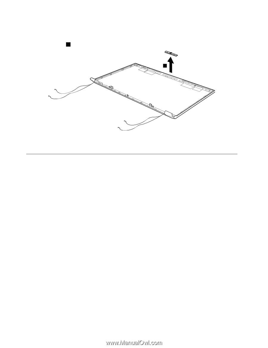
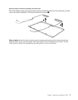
Removal steps of integrated camera Note: The integrated camera is stuck on the top center of the LCD cover. Remove the integrated camera from the LCD cover 1 . 1 When installing: Stick the integrated camera to the top center of the LCD cover and ajust the placement of it to make sure the connector is attached firmly. 1180 Antenna assembly and LCD cover For access, remove these FRUs in order: • "1010 Battery pack" on page 46 • "1020 Dummy card" on page 47 • "1030 Hard disk drive (HDD)/memory module/mini PCI Express Card slot compartment cover" on page 47 • "1040 Hard disk drive" on page 48 • "1050 Optical drive" on page 49 • "1060 Memory module" on page 50 • "1070 PCI Express Mini Card for wireless LAN/WAN" on page 51 • "1080 Keyboard" on page 53 • "1090 Keyboard bezel" on page 54 • "1100 System board assembly" on page 56 • "1110 LCD unit" on page 58 • "1150 LCD front bezel" on page 66 • "1160 LCD panel, LCD cable, and hinges" on page 67 70 Hardware Maintenance Manual
-
 1
1 -
2
-
3
-
4
-
5
-
6
-
7
-
8
-
9
-
10
-
11
-
12
-
13
-
14
-
15
-
16
-
17
-
18
-
19
-
20
-
21
-
22
-
23
-
24
-
25
-
26
-
27
-
28
-
29
-
30
-
31
-
32
-
33
-
34
-
35
-
36
-
37
-
38
-
39
-
40
-
41
-
42
-
43
-
44
-
45
-
46
-
47
-
48
-
49
-
50
-
51
-
52
-
53
-
54
-
55
-
56
-
57
-
58
-
59
-
60
-
61
-
62
-
63
-
64
-
65
-
66
-
67
-
68
-
69
-
70
-
 71
71 -
 72
72 -
 73
73 -
 74
74 -
 75
75 -
 76
76 -
 77
77 -
 78
78 -
 79
79 -
 80
80 -
 81
81 -
82
-
83
-
84
-
85
-
86
-
87
-
88
-
89
-
90
-
91
-
92
-
93
-
94
-
95
-
96
 |
 |