Lenovo G505 Hardware Maintenance Manual - Lenovo G400, G500, G405, G505, G410, - Page 58
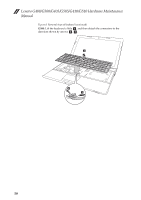
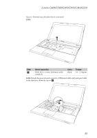
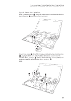
Remove the keyboard bezel in the direction shown by arrow
 |
View all Lenovo G505 manuals
Add to My Manuals
Save this manual to your list of manuals |
Page 58 highlights
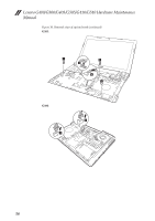
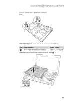
Lenovo G400/G500/G405/G505/G410/G510 Hardware Maintenance Manual Figure 9. Removal steps of keyboard bezel (continued) G500: Detach the power board connector and touch pad cable in the direction shown by arrow e . e When installing: Make sure that the power board connector and touch pad cable are attached firmly. Remove the keyboard bezel in the direction shown by arrow f. f 54
-
 1
1 -
2
-
3
-
4
-
5
-
6
-
7
-
8
-
9
-
10
-
11
-
12
-
13
-
14
-
15
-
16
-
17
-
18
-
19
-
20
-
21
-
22
-
23
-
24
-
25
-
26
-
27
-
28
-
29
-
30
-
31
-
32
-
33
-
34
-
35
-
36
-
37
-
38
-
39
-
40
-
41
-
42
-
43
-
44
-
45
-
46
-
47
-
48
-
49
-
50
-
51
-
52
-
 53
53 -
 54
54 -
 55
55 -
 56
56 -
 57
57 -
 58
58 -
 59
59 -
 60
60 -
 61
61 -
 62
62 -
 63
63 -
64
-
65
-
66
-
67
-
68
-
69
-
70
-
71
-
72
-
73
-
74
-
75
-
76
-
77
-
78
-
79
-
80
-
81
-
82
-
83
-
84
-
85
-
86
-
87
-
88
-
89
-
90
-
91
-
92
-
93
-
94
-
95
-
96
-
97
-
98
-
99
-
100
-
101
-
102
-
103
-
104
-
105
-
106
-
107
-
108
 |
 |
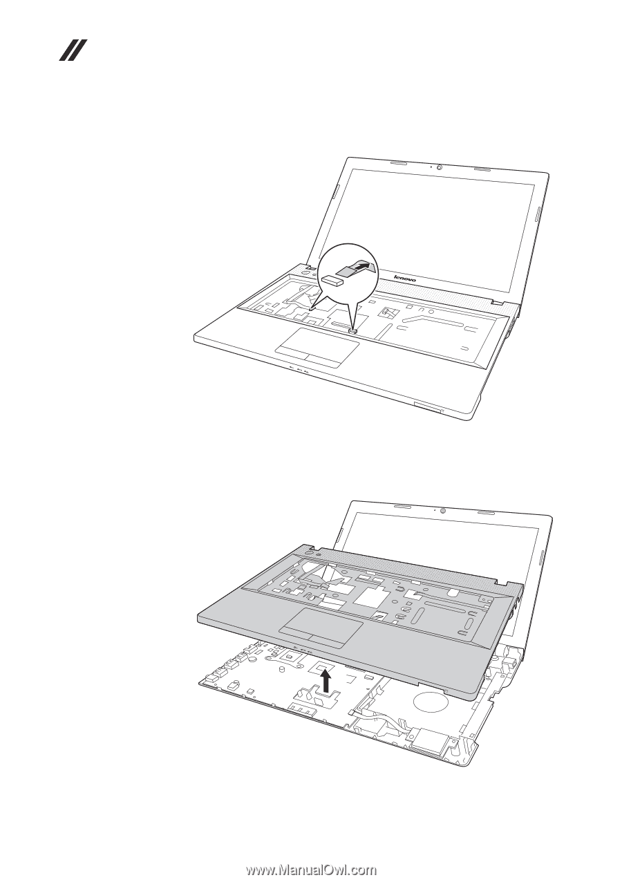
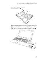
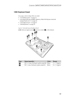
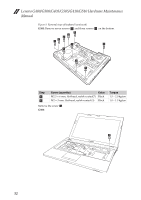
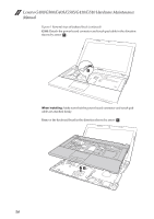
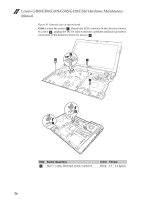
Lenovo G400/G500/G405/G505/G410/G510 Hardware Maintenance
Manual
54
Figure 9. Removal steps of keyboard bezel (continued)
G500:
Detach the power board connector and touch pad cable in the direction
shown by arrow
.
When installing:
Make sure that the power board connector and touch pad
cable are attached firmly.
Remove the keyboard bezel in the direction shown by arrow
.
e
e
f
f