Lenovo G505 Hardware Maintenance Manual - Lenovo G400, G500, G405, G505, G410, - Page 78
LCD panel, LCD cable and hinges
 |
View all Lenovo G505 manuals
Add to My Manuals
Save this manual to your list of manuals |
Page 78 highlights
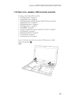
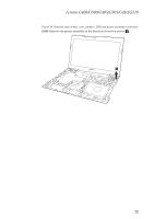
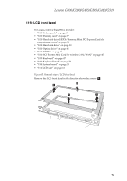
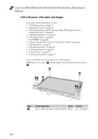
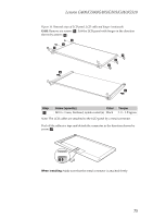
Lenovo G400/G500/G405/G505/G410/G510 Hardware Maintenance Manual 1160 LCD panel, LCD cable and hinges For access, remove these FRUs in order: • "1010 Battery pack" on page 36 • "1020 Dummy card" on page 37 • "1030 Hard disk drive(HDD)/Memory/Mini PCI Express Card slot compartment cover" on page 38 • "1040 Hard disk drive" on page 39 • "1050 Optical drive" on page 42 • "1060 DIMM" on page 44 • "1070 PCI Express Mini Card for wireless LAN/WAN" on page 45 • "1080 Keyboard" on page 47 • "1090 Keyboard bezel" on page 51 • "1100 System board" on page 55 • "1110 LCD unit" on page 61 • "1150 LCD front bezel" on page 73 Figure 16. Removal steps of LCD panel, LCD cable and hinges G400: Remove six screws a and the hinges in the direction shown by arrows b. a a aa b b aa Step a Screw (quantity) Color M2.5 × 4 mm, flat-head, nylok-coated (6) Black Torque 2.0 ~ 2.5 kgfcm 74
-
 1
1 -
2
-
3
-
4
-
5
-
6
-
7
-
8
-
9
-
10
-
11
-
12
-
13
-
14
-
15
-
16
-
17
-
18
-
19
-
20
-
21
-
22
-
23
-
24
-
25
-
26
-
27
-
28
-
29
-
30
-
31
-
32
-
33
-
34
-
35
-
36
-
37
-
38
-
39
-
40
-
41
-
42
-
43
-
44
-
45
-
46
-
47
-
48
-
49
-
50
-
51
-
52
-
53
-
54
-
55
-
56
-
57
-
58
-
59
-
60
-
61
-
62
-
63
-
64
-
65
-
66
-
67
-
68
-
69
-
70
-
71
-
72
-
 73
73 -
 74
74 -
 75
75 -
 76
76 -
 77
77 -
 78
78 -
 79
79 -
 80
80 -
 81
81 -
 82
82 -
 83
83 -
84
-
85
-
86
-
87
-
88
-
89
-
90
-
91
-
92
-
93
-
94
-
95
-
96
-
97
-
98
-
99
-
100
-
101
-
102
-
103
-
104
-
105
-
106
-
107
-
108
 |
 |