Lenovo G710 Laptop Hardware Maintenance Manual - Lenovo G700, G710 - Page 42
Optical drive
 |
View all Lenovo G710 Laptop manuals
Add to My Manuals
Save this manual to your list of manuals |
Page 42 highlights
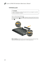
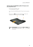
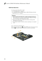
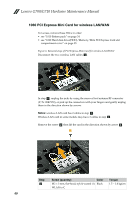
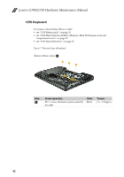
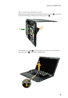
Lenovo G700/G710 Hardware Maintenance Manual 1040 Optical drive For access, remove this FRU: • see "1010 Battery pack" on page 34 • see "1020 Hard disk drive(HDD)/Memory/Mini PCI Express Card slot compartment cover" on page 35 Figure 4. Removal steps of optical drive Remove the screw a, then pull the optical drive out in the direction shown by arrow b . 1 2 Step a Screw (quantity) M2 × 6 mm,flat-head, nylok-coated(1) ODD BD to D Color Black Torque 2.0 ~ 2.5 kgfcm 38
-
 1
1 -
2
-
3
-
4
-
5
-
6
-
7
-
8
-
9
-
10
-
11
-
12
-
13
-
14
-
15
-
16
-
17
-
18
-
19
-
20
-
21
-
22
-
23
-
24
-
25
-
26
-
27
-
28
-
29
-
30
-
31
-
32
-
33
-
34
-
35
-
36
-
 37
37 -
 38
38 -
 39
39 -
 40
40 -
 41
41 -
 42
42 -
 43
43 -
 44
44 -
 45
45 -
 46
46 -
 47
47 -
48
-
49
-
50
-
51
-
52
-
53
-
54
-
55
-
56
-
57
-
58
-
59
-
60
-
61
-
62
-
63
-
64
-
65
-
66
-
67
-
68
-
69
-
70
-
71
-
72
-
73
-
74
-
75
-
76
-
77
-
78
-
79
-
80
-
81
-
82
-
83
-
84
-
85
-
86
-
87
-
88
 |
 |

Lenovo G700/G710 Hardware Maintenance Manual
38
1040 Optical drive
For access, remove this FRU:
•
see “1010 Battery pack” on page 34
•
see “1020 Hard disk drive(HDD)/Memory/Mini PCI Express Card slot
compartment cover” on page 35
Figure 4. Removal steps of optical drive
Remove the screw
, then pull the optical drive out in the direction shown by
arrow
.
Step
Screw (quantity)
Color
Torque
M2 × 6 mm,flat-head, nylok-coated(1)
ODD BD to D
Black
2.0 ~ 2.5 kgfcm
a
b
1
2
a