Lenovo G710 Laptop Hardware Maintenance Manual - Lenovo G700, G710 - Page 66
Hinge to Panel, Removal steps of LCD panel, LCD cable, antenna assembly, and hinges
 |
View all Lenovo G710 Laptop manuals
Add to My Manuals
Save this manual to your list of manuals |
Page 66 highlights
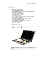
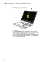
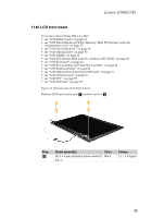
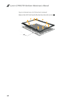
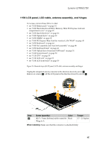
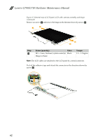
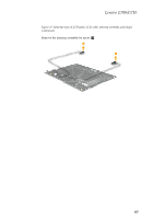
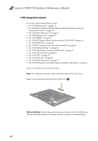
Lenovo G700/G710 Hardware Maintenance Manual Figure 15. Removal steps of LCD panel, LCD cable, antenna assembly, and hinges (continued) Remove six screws d and remove the hinges in the direction shown by arrows e. 5 4 5 4 Step d Screw (quantity) Color M2 × 3 mm, flat-head, nylok-coated (6) Black Hinge to Panel Torque 1.0 ~ 1.5 kgfcm Note: The LCD cables are attached to the LCD panel by a metal connector. Peel off the adhesive tape and detach the connector in the direction shown by arrow f. 6 62
-
 1
1 -
2
-
3
-
4
-
5
-
6
-
7
-
8
-
9
-
10
-
11
-
12
-
13
-
14
-
15
-
16
-
17
-
18
-
19
-
20
-
21
-
22
-
23
-
24
-
25
-
26
-
27
-
28
-
29
-
30
-
31
-
32
-
33
-
34
-
35
-
36
-
37
-
38
-
39
-
40
-
41
-
42
-
43
-
44
-
45
-
46
-
47
-
48
-
49
-
50
-
51
-
52
-
53
-
54
-
55
-
56
-
57
-
58
-
59
-
60
-
 61
61 -
 62
62 -
 63
63 -
 64
64 -
 65
65 -
 66
66 -
 67
67 -
 68
68 -
 69
69 -
 70
70 -
 71
71 -
72
-
73
-
74
-
75
-
76
-
77
-
78
-
79
-
80
-
81
-
82
-
83
-
84
-
85
-
86
-
87
-
88
 |
 |

Lenovo G700/G710 Hardware Maintenance Manual
62
Figure 15. Removal steps of LCD panel, LCD cable, antenna assembly, and hinges
(continued)
Remove six screws
and remove the hinges in the direction shown by arrows
.
Note:
The LCD cables are attached to the LCD panel by a metal connector.
Peel off the adhesive tape and detach the connector in the direction shown by
arrow
Step
Screw (quantity)
Color
Torque
M2 × 3 mm, flat-head, nylok-coated (6)
Hinge to Panel
Black
1.0 ~ 1.5 kgfcm
d
e
4
4
5
5
d
f
6