Lenovo H520 Lenovo H520s Hardware Maintenance Manual - Page 28
Font view, Attention - memory
 |
View all Lenovo H520 manuals
Add to My Manuals
Save this manual to your list of manuals |
Page 28 highlights
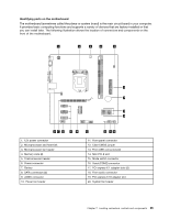
Font view The following illustration shows the location of controls and components on the front of the computer. Attention: Be careful not to block any air vents on the computer. Blocked air vents can cause overheating. 1. Power button 2. Memory card reader (selected models only) 3. USB connectors 4. Optical drive eject button 5. Headphone connector 6. Optical Drive (selected models only) 7. Hard disk drive indicator 8. Microphone connector Attention: The effective range of the Built-in IR Emitter is 10 feet (3m). 22 Lenovo H520sHardware Maintenance Manual
-
 1
1 -
2
-
3
-
4
-
5
-
6
-
7
-
8
-
9
-
10
-
11
-
12
-
13
-
14
-
15
-
16
-
17
-
18
-
19
-
20
-
21
-
22
-
 23
23 -
 24
24 -
 25
25 -
 26
26 -
 27
27 -
 28
28 -
 29
29 -
 30
30 -
 31
31 -
 32
32 -
 33
33 -
34
-
35
-
36
-
37
-
38
-
39
-
40
-
41
-
42
-
43
-
44
-
45
-
46
-
47
-
48
-
49
-
50
-
51
-
52
-
53
-
54
-
55
-
56
-
57
-
58
-
59
 |
 |
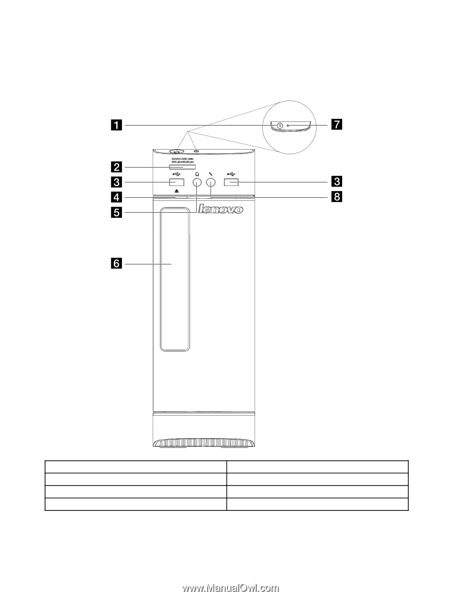
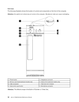
Font view
The following illustration shows the location of controls and components on the front of the computer.
Attention:
Be careful not to block any air vents on the computer. Blocked air vents can cause overheating.
1. Power button
5. Headphone connector
2. Memory card reader (selected models only)
6. Optical Drive (selected models only)
3. USB connectors
7. Hard disk drive indicator
4. Optical drive eject button
8. Microphone connector
Attention:
The effective range of the Built-in IR Emitter is 10 feet (3m).
22
Lenovo H520sHardware Maintenance Manual