Lenovo IdeaPad Y560 Lenovo IdeaPad Y560 Hardware Maintenance Manual V2.0 - Page 80
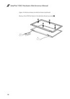
Removal steps of LCD panel, LCD cable and hinges continued, Remove two screws
 |
View all Lenovo IdeaPad Y560 manuals
Add to My Manuals
Save this manual to your list of manuals |
Page 80 highlights
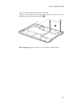
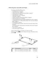
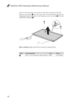
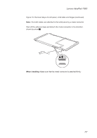
IdeaPad Y560 Hardware Maintenance Manual Figure 19. Removal steps of LCD panel, LCD cable and hinges (continued) Remove two screws 4. Lift the lower side of the LCD panel, detach the integrated camera connector in the direction shown by arrow 5 and then remove the LCD panel 6. 4 5 4 6 When installing: Make sure that the connector is attached firmly. Step 5 Screw (quantity) Color M2.0 × 3.5 mm, flat-head, nylok-coated (2) Black Torque 1.5±0.2 kgfcm 76
-
 1
1 -
2
-
3
-
4
-
5
-
6
-
7
-
8
-
9
-
10
-
11
-
12
-
13
-
14
-
15
-
16
-
17
-
18
-
19
-
20
-
21
-
22
-
23
-
24
-
25
-
26
-
27
-
28
-
29
-
30
-
31
-
32
-
33
-
34
-
35
-
36
-
37
-
38
-
39
-
40
-
41
-
42
-
43
-
44
-
45
-
46
-
47
-
48
-
49
-
50
-
51
-
52
-
53
-
54
-
55
-
56
-
57
-
58
-
59
-
60
-
61
-
62
-
63
-
64
-
65
-
66
-
67
-
68
-
69
-
70
-
71
-
72
-
73
-
74
-
 75
75 -
 76
76 -
 77
77 -
 78
78 -
 79
79 -
 80
80 -
 81
81 -
 82
82 -
 83
83 -
 84
84 -
 85
85 -
86
-
87
-
88
-
89
-
90
-
91
-
92
-
93
-
94
-
95
-
96
-
97
-
98
-
99
-
100
-
101
-
102
-
103
 |
 |

76
IdeaPad Y560 Hardware Maintenance Manual
Figure 19. Removal steps of LCD panel, LCD cable and hinges (continued)
Remove two screws
4
. Lift the lower side of the LCD panel, detach the
integrated camera connector in the direction shown by arrow
5
and then
remove the LCD panel
6
.
6
4
4
5
When installing:
Make sure that the connector is attached firmly.
Step
Screw (quantity)
Color
Torque
5
M2.0 × 3.5 mm, flat-head, nylok-coated (2)
Black
1.5±0.2 kgfcm