Lenovo ThinkCentre A35 (English) User guide for ThinkCentre A35 (type 8139) sy - Page 41
Replacing, cover, connecting, cables
 |
View all Lenovo ThinkCentre A35 manuals
Add to My Manuals
Save this manual to your list of manuals |
Page 41 highlights
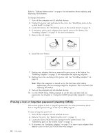
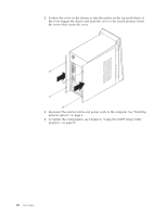
5. Move the jumper from the standard position (pins 1 and 2) to the maintenance or configure position (pins 2 and 3). Note: If only two pins exist on the system board, place the jumper across the two pins. 6. Replace the cover and connect the power cord. See "Replacing the cover and connecting the cables." 7. Restart the computer, leave it on for approximately 10 seconds. Turn off the computer by holding the power switch for approximately 5 seconds. The computer will turn off. 8. Repeat steps 2 through 4 on page 24.. 9. Move the jumper back to the standard (pins 1 and 2). 10. Replace the cover and connect the power cord. See "Replacing the cover and connecting the cables." Replacing the cover and connecting the cables After working with options, you need to install any removed parts, replace the cover, and reconnect any cables, including telephone lines and power cords. Also, depending on the option that is installed, you might need to confirm the updated information in the CMOS Setup Utility program. To replace the cover and connect cables to your computer: 1. Ensure that all components have been reassembled correctly and that no tools or loose screws are left inside your computer. 2. Clear any cables that might impede the replacement of the cover. Chapter 1. Installing options 25
-
 1
1 -
2
-
3
-
4
-
5
-
6
-
7
-
8
-
9
-
10
-
11
-
12
-
13
-
14
-
15
-
16
-
17
-
18
-
19
-
20
-
21
-
22
-
23
-
24
-
25
-
26
-
27
-
28
-
29
-
30
-
31
-
32
-
33
-
34
-
35
-
 36
36 -
 37
37 -
 38
38 -
 39
39 -
 40
40 -
 41
41 -
 42
42 -
 43
43 -
 44
44 -
 45
45 -
 46
46 -
47
-
48
-
49
-
50
-
51
-
52
-
53
-
54
-
55
-
56
-
57
-
58
-
59
-
60
-
61
-
62
-
63
-
64
 |
 |