Lenovo ThinkPad Yoga 14 (English) Hardware Maintenance Manual - ThinkPad Yoga
Lenovo ThinkPad Yoga 14 Manual
 |
View all Lenovo ThinkPad Yoga 14 manuals
Add to My Manuals
Save this manual to your list of manuals |
Lenovo ThinkPad Yoga 14 manual content summary:
- Lenovo ThinkPad Yoga 14 | (English) Hardware Maintenance Manual - ThinkPad Yoga - Page 1
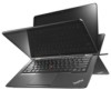
Hardware Maintenance Manual ThinkPad Yoga 14 - Lenovo ThinkPad Yoga 14 | (English) Hardware Maintenance Manual - ThinkPad Yoga - Page 2
and the product it supports, be sure to read the general information under Appendix A "Notices" on page 91. First Edition (October 2014) © Copyright Lenovo 2014. LIMITED AND RESTRICTED RIGHTS NOTICE: If data or software is delivered pursuant a General Services Administration "GSA" contract, use - Lenovo ThinkPad Yoga 14 | (English) Hardware Maintenance Manual - ThinkPad Yoga - Page 3
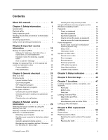
20 How to use error message 20 Strategy for replacing FRUs for CTO, special bid model, and standard models 20 Product definition 20 FRU identification 21 Chapter 3. General checkout . . . . . 23 What to do first 23 Checkout guide 24 Lenovo Solution Center 24 Quick test programs 24 UEFI - Lenovo ThinkPad Yoga 14 | (English) Hardware Maintenance Manual - ThinkPad Yoga - Page 4
guidelines 59 Before servicing the computer 60 Disabling the built-in battery 60 1010 Lenovo-OneLink-connector cover . . . . . 60 1020 Keyboard 61 1030 Base cover assembly 63 1040 Battery pack 65 1050 Internal storage drive and the storage drive connector 66 1060 Memory module 67 1070 - Lenovo ThinkPad Yoga 14 | (English) Hardware Maintenance Manual - ThinkPad Yoga - Page 5
this manual This manual contains service and reference information for the following ThinkPad® products. ThinkPad Yoga 14 Machine type (MT) 20DM and 20DN Use this manual along with the advanced diagnostic tests to troubleshoot problems. Important: This manual is intended only for trained service - Lenovo ThinkPad Yoga 14 | (English) Hardware Maintenance Manual - ThinkPad Yoga - Page 6
iv Hardware Maintenance Manual - Lenovo ThinkPad Yoga 14 | (English) Hardware Maintenance Manual - ThinkPad Yoga - Page 7
service a ThinkPad notebook computer. • "General safety" on page 1 • "Electrical safety" on page 1 • "Safety inspection guide move suddenly or twist parts in a safe place, away from all personnel, while you are servicing service, reinstall all safety shields, guards, labels, and ground wires. Replace - Lenovo ThinkPad Yoga 14 | (English) Hardware Maintenance Manual - ThinkPad Yoga - Page 8
voltages; Instructions for Do not service the following parts with the power fans - Motor generators - Parts similar to those listed above guide The purpose of this inspection guide is service technicians from injury. This guide ThinkPad features or options not covered by this inspection guide - Lenovo ThinkPad Yoga 14 | (English) Hardware Maintenance Manual - ThinkPad Yoga - Page 9
conditions, use the following checklist at the beginning of every service task. Begin the checks with the power off, and the lenovo.com/serviceparts-lookup c. Insulation must not be frayed or worn. 4. Check for cracked or bulging batteries. 5. Remove the cover. 6. Check for any obvious non-ThinkPad - Lenovo ThinkPad Yoga 14 | (English) Hardware Maintenance Manual - ThinkPad Yoga - Page 10
- When working on a double-insulated or battery-operated system, use an ESD common ground or reference point. You can use coax or connector • Arabic • Brazilian Portuguese • French • German • Hebrew • Japanese • Korean • Spanish • Traditional Chinese DANGER DANGER DANGER 4 Hardware Maintenance Manual - Lenovo ThinkPad Yoga 14 | (English) Hardware Maintenance Manual - ThinkPad Yoga - Page 11
DANGER DANGER DANGER DANGER DANGER Chapter 1. Safety information 5 - Lenovo ThinkPad Yoga 14 | (English) Hardware Maintenance Manual - ThinkPad Yoga - Page 12
6 Hardware Maintenance Manual - Lenovo ThinkPad Yoga 14 | (English) Hardware Maintenance Manual - ThinkPad Yoga - Page 13
PERIGO PERIGO PERIGO PERIGO Chapter 1. Safety information 7 - Lenovo ThinkPad Yoga 14 | (English) Hardware Maintenance Manual - ThinkPad Yoga - Page 14
PERIGO PERIGO PERIGO PERIGO DANGER 8 Hardware Maintenance Manual - Lenovo ThinkPad Yoga 14 | (English) Hardware Maintenance Manual - ThinkPad Yoga - Page 15
DANGER DANGER DANGER DANGER DANGER DANGER Chapter 1. Safety information 9 - Lenovo ThinkPad Yoga 14 | (English) Hardware Maintenance Manual - ThinkPad Yoga - Page 16
DANGER VORSICHT VORSICHT VORSICHT VORSICHT 10 Hardware Maintenance Manual - Lenovo ThinkPad Yoga 14 | (English) Hardware Maintenance Manual - ThinkPad Yoga - Page 17
VORSICHT VORSICHT VORSICHT VORSICHT Chapter 1. Safety information 11 - Lenovo ThinkPad Yoga 14 | (English) Hardware Maintenance Manual - ThinkPad Yoga - Page 18
12 Hardware Maintenance Manual - Lenovo ThinkPad Yoga 14 | (English) Hardware Maintenance Manual - ThinkPad Yoga - Page 19
Chapter 1. Safety information 13 - Lenovo ThinkPad Yoga 14 | (English) Hardware Maintenance Manual - ThinkPad Yoga - Page 20
14 Hardware Maintenance Manual - Lenovo ThinkPad Yoga 14 | (English) Hardware Maintenance Manual - ThinkPad Yoga - Page 21
Chapter 1. Safety information 15 - Lenovo ThinkPad Yoga 14 | (English) Hardware Maintenance Manual - ThinkPad Yoga - Page 22
16 Hardware Maintenance Manual - Lenovo ThinkPad Yoga 14 | (English) Hardware Maintenance Manual - ThinkPad Yoga - Page 23
Chapter 1. Safety information 17 - Lenovo ThinkPad Yoga 14 | (English) Hardware Maintenance Manual - ThinkPad Yoga - Page 24
18 Hardware Maintenance Manual - Lenovo ThinkPad Yoga 14 | (English) Hardware Maintenance Manual - ThinkPad Yoga - Page 25
fixes, drivers, and UEFI BIOS, go to http://www.lenovo.com/ThinkPadDrivers and follow the instructions on the screen. Use the following strategy to prevent unnecessary expense for replacing and servicing FRUs: • If you are instructed to replace a FRU but the replacement does not correct the problem - Lenovo ThinkPad Yoga 14 | (English) Hardware Maintenance Manual - ThinkPad Yoga - Page 26
installing it on the computer you are servicing. Otherwise, the mSATA solid-state drive will not function correctly. For instructions on how to partition an mSATA solid-state drive, go tohttp://www.lenovo.com/support/msata-fru. Important notice for replacing a system board Some components mounted on - Lenovo ThinkPad Yoga 14 | (English) Hardware Maintenance Manual - ThinkPad Yoga - Page 27
of major FRUs are hard disk drive, system board, liquid crystal display (LCD), and memory module. To identify the major FRUs for a product, do the following: 1. Go to http://www.lenovo.com/support. 2. Click Warranty & Services. 3. Click Check Warranty Status. 4. On the Warranty Status Lookup page - Lenovo ThinkPad Yoga 14 | (English) Hardware Maintenance Manual - ThinkPad Yoga - Page 28
22 Hardware Maintenance Manual - Lenovo ThinkPad Yoga 14 | (English) Hardware Maintenance Manual - ThinkPad Yoga - Page 29
. Consider replacing a FRU only when a problem recurs. If parts exchange form or parts return form that you attach to it: 1. Name and phone number of service technician 2. Date of service 3. Date on which the machine failed 4. Date of purchase 5. Failure symptoms, error codes appearing on the display - Lenovo ThinkPad Yoga 14 | (English) Hardware Maintenance Manual - ThinkPad Yoga - Page 30
, and then follow the instructions on the screen. For more information about the Lenovo Solution Center program, refer to the help information system of the program. Quick test programs Run quick test programs to troubleshoot and resolve computer problems, especially when the computer does - Lenovo ThinkPad Yoga 14 | (English) Hardware Maintenance Manual - ThinkPad Yoga - Page 31
program, go to http://www.lenovo.com/diags, and follow the instructions on the Web site. To troubleshooting hints. 2. When the ThinkPad logo is displayed, repeatedly press and release the F10 key. The main screen of the UEFI diagnostic program is displayed. 3. Follow the instructions on the screen - Lenovo ThinkPad Yoga 14 | (English) Hardware Maintenance Manual - ThinkPad Yoga - Page 32
3. When the ThinkPad logo is displayed, repeatedly press and release the F12 key. When the Boot Menu window opens, release the F12 key. 4. Use the arrow keys to select USB HDD and then press Enter. The diagnostic program will be launched automatically. 5. Follow the instructions on the screen to use - Lenovo ThinkPad Yoga 14 | (English) Hardware Maintenance Manual - ThinkPad Yoga - Page 33
• "Checking the coin-cell battery" on page 28 Checking the ac power adapter You are here because the computer fails only when the ac power adapter is used. • If the power problem occurs only when the docking station or the port replicator is used, replace the docking station or the port replicator - Lenovo ThinkPad Yoga 14 | (English) Hardware Maintenance Manual - ThinkPad Yoga - Page 34
. Wire Red Black Voltage (V dc) +2.5 to +3.2 Ground • If the voltage is correct, replace the system board. • If the voltage is not correct, replace the coin-cell battery. • If the coin-cell battery discharges quickly after replacement, replace the system board. 28 Hardware Maintenance Manual - Lenovo ThinkPad Yoga 14 | (English) Hardware Maintenance Manual - ThinkPad Yoga - Page 35
service diskette become available, they will be posted on http://www.lenovo.com/support Restoring the factory contents by using the Recovery Disc Set When the main storage drive is replaced user instructions and screen is displayed or when you hear repeating beeps, release the F1 key. The ThinkPad - Lenovo ThinkPad Yoga 14 | (English) Hardware Maintenance Manual - ThinkPad Yoga - Page 36
instructions on the screen. 6. Click Yes in the displayed window to begin the operating system recovery process. 7. Insert the Applications and Drivers as backups or replacement for the Windows recovery image. With the recovery media, you can troubleshoot and fix the problems on your computer - Lenovo ThinkPad Yoga 14 | (English) Hardware Maintenance Manual - ThinkPad Yoga - Page 37
screen to display the charms. Click Settings ➙ Change PC settings ➙ Update and recovery ➙ Recovery. 2. In the Advanced startup section, click Restart now ➙ Troubleshoot ➙ Advanced options. 3. Select a desired startup option, then follow the instructions on the screen 4. Related service information 31 - Lenovo ThinkPad Yoga 14 | (English) Hardware Maintenance Manual - ThinkPad Yoga - Page 38
options by following the instructions on the screen. Note: Ensure that your you can use recovery media to troubleshoot and fix the problems on your computer. It is recommended to the top-right or bottom-right corner of the screen to display the charms, and click Search. 2. Depending on the Manual - Lenovo ThinkPad Yoga 14 | (English) Hardware Maintenance Manual - ThinkPad Yoga - Page 39
select a preferred keyboard layout. 4. Click Troubleshoot to display the optional recovery the computer your are servicing does not perform well and the problem might be caused by 1. Move your cursor to the bottom-right corner of the screen to bring up the charms. Click Settings ➙ Change PC - Lenovo ThinkPad Yoga 14 | (English) Hardware Maintenance Manual - ThinkPad Yoga - Page 40
➙ Troubleshoot ➙ Advanced options. 3. Restart the computer following the instructions on the screen. Lenovo authorized service technicians provide any services to reset either the user or the master hard disk password, or to recover data from the hard disk drive. The hard disk drive can be replaced - Lenovo ThinkPad Yoga 14 | (English) Hardware Maintenance Manual - ThinkPad Yoga - Page 41
battery. For instructions on how to install the coin-cell battery, see "1080 Coin-cell battery" on page 69. 5. Reinstall the battery pack. For instructions on how to install the battery pack, see "1040 Battery exit the ThinkPad Setup Lenovo and Lenovo-authorized service solution would be to replace - Lenovo ThinkPad Yoga 14 | (English) Hardware Maintenance Manual - ThinkPad Yoga - Page 42
8. Press F10. 9. Press F10 to save changes and exit the ThinkPad Setup program. The user hard disk password and the master hard disk computer into screen blank mode, do the following: 1. Right-click the battery gauge on the taskbar. 2. Select Power off display. To end screen blank mode Manual - Lenovo ThinkPad Yoga 14 | (English) Hardware Maintenance Manual - ThinkPad Yoga - Page 43
is displayed, check the narrative descriptions of symptoms. If the symptom is not described there, go to "Intermittent problems" on page 40. Note: For a device not supported by diagnostic codes in the ThinkPad notebook computers, see the manual for that device. Chapter 4. Related service information - Lenovo ThinkPad Yoga 14 | (English) Hardware Maintenance Manual - ThinkPad Yoga - Page 44
Setup to reset the time and date 2. Replace the coin-cell battery and run ThinkPad Setup to reset the time and date. 1. Remove network card. 2. Replace the system board. Remove all but the reader that you set up for the authentication. Have the computer serviced. 1. Reseat the hard disk drive - Lenovo ThinkPad Yoga 14 | (English) Hardware Maintenance Manual - ThinkPad Yoga - Page 45
the mini SATA device. 3. Replace the system board. Replace the system board. Replace the system board. Error messages Table 3. Error messages Symptom or error Fan error. Thermal sensing error. This system does not support batteries that are not genuine Lenovo-made or authorized. The system will - Lenovo ThinkPad Yoga 14 | (English) Hardware Maintenance Manual - ThinkPad Yoga - Page 46
LCD you are servicing has two or less visible defective pixels, it should not be considered faulty. However, if the LCD has three or more visible defective pixels, it will be deemed as defective by Lenovo and it should be replaced. Notes: • This policy applies to all ThinkPad notebooks purchased on - Lenovo ThinkPad Yoga 14 | (English) Hardware Maintenance Manual - ThinkPad Yoga - Page 47
following devices: a. Non-ThinkPad devices b. Devices attached to the docking station or the port replicator c. Printer, mouse, and other external devices d. Battery pack e. Hard disk drive, hybrid drive, or solid-state drive f. External diskette drive or optical drive g. Memory module h. PC cards - Lenovo ThinkPad Yoga 14 | (English) Hardware Maintenance Manual - ThinkPad Yoga - Page 48
42 Hardware Maintenance Manual - Lenovo ThinkPad Yoga 14 | (English) Hardware Maintenance Manual - ThinkPad Yoga - Page 49
indicator 2 Microphone mute indicator 3 Camera status indicator Meaning On: The speakers are muted. On: The microphones are muted. On: The camera is in use. © Copyright Lenovo 2014 43 - Lenovo ThinkPad Yoga 14 | (English) Hardware Maintenance Manual - ThinkPad Yoga - Page 50
or in hibernation mode. Slow blinking: The computer is in sleep mode. Fast blinking: The computer is entering sleep or hibernation mode. 44 Hardware Maintenance Manual - Lenovo ThinkPad Yoga 14 | (English) Hardware Maintenance Manual - ThinkPad Yoga - Page 51
Mutes or unmutes the microphones. Darkens the display. Brightens the display. Switches the display output location between the computer display and an external monitor. Enables or disables 7: Opens Computer. For Windows 8 and Windows 8.1: Views all the programs. © Copyright Lenovo 2014 45 - Lenovo ThinkPad Yoga 14 | (English) Hardware Maintenance Manual - ThinkPad Yoga - Page 52
46 Hardware Maintenance Manual - Lenovo ThinkPad Yoga 14 | (English) Hardware Maintenance Manual - ThinkPad Yoga - Page 53
-control buttons 9 System-status indicator 11 TrackPoint® pointing stick 13 Multi-touch screen 8 7 655 4 2 Camera 4 High-Definition Multimedia Interface (HDMI™) connector 6 Screen-rotation-lock button 8 Power button 10 ThinkPad trackpad 12 Windows Start screen control © Copyright Lenovo 2014 47 - Lenovo ThinkPad Yoga 14 | (English) Hardware Maintenance Manual - ThinkPad Yoga - Page 54
Bottom view 2 1 1 Emergency-reset hole Rear view 2 2 Speakers 1 7 1 System-status indicator (illuminated ThinkPad logo) 3 Audio connector 5 Lenovo OneLink connector 7 Fan louvers 2 3 4 65 2 Media card slot 4 Always On USB connector (USB 2.0 connector) 6 ac power connector 48 Hardware - Lenovo ThinkPad Yoga 14 | (English) Hardware Maintenance Manual - ThinkPad Yoga - Page 55
this Hardware Maintenance Manual. An electronic version of this manual can be found at http://www.lenovo.com/support. Click Guides & Manuals and then follow the on-screen instructions to find the manual for your product. You might be required to return the defective part that is replaced by the CRU - Lenovo ThinkPad Yoga 14 | (English) Hardware Maintenance Manual - ThinkPad Yoga - Page 56
2 17 3 16 15 4 14 13 12 5 11 6 7 10 8 9 a Table 9. Major CRUs and FRUs No. CRUs or FRU descriptions Self-service CRU a Base cover assembly rubber caps. See "Miscellaneous parts and No other FRUs" on page 53 1 LCD unit No 2 Keyboard bezel assembly No 3 ThinkPad-logo-LED card No - Lenovo ThinkPad Yoga 14 | (English) Hardware Maintenance Manual - ThinkPad Yoga - Page 57
power card with cable and bracket 12 Media card reader 13 M.2 solid-state drive 14 Wireless LAN card 15 Coin-cell battery 16 Memory module 17 Thermal fan assembly 18 Lenovo-OneLink-connector cover 19 Keyboard 20 TrackPoint cap Self-service CRU Yes No Yes No No No No Yes Yes Yes Yes Yes No Yes - Lenovo ThinkPad Yoga 14 | (English) Hardware Maintenance Manual - ThinkPad Yoga - Page 58
b LCD bezel rubber caps. See "Miscellaneous parts and other FRUs" on page 53 1 LCD ThinkPad-LED-logo card with cable 7 LCD cover assembly 8 Touch control board 9 Windows-Start-screen-button vibrator 10 LCD hinge assembly 11 LCD hinge rubber clips 12 LCD cable 13 LCD bezel assembly Self-service - Lenovo ThinkPad Yoga 14 | (English) Hardware Maintenance Manual - ThinkPad Yoga - Page 59
Power cord Self-service CRU No No No Optional service CRU No No No Self-service CRU Yes Yes Optional service CRU No No Looking up FRU information For detailed FRU information, including part numbers, descriptions, and substitution part numbers, go to: http://www.lenovo.com/serviceparts-lookup - Lenovo ThinkPad Yoga 14 | (English) Hardware Maintenance Manual - ThinkPad Yoga - Page 60
54 Hardware Maintenance Manual - Lenovo ThinkPad Yoga 14 | (English) Hardware Maintenance Manual - ThinkPad Yoga - Page 61
this Hardware Maintenance Manual. An electronic version of this manual can be found at http://www.lenovo.com/support. Click Guides & Manuals and then follow the on-screen instructions to find the manual for your product. You might be required to return the defective part that is replaced by the CRU - Lenovo ThinkPad Yoga 14 | (English) Hardware Maintenance Manual - ThinkPad Yoga - Page 62
the life of the computer. If you replace the ThinkPad Setup program is set to UEFI Only. 1. Connect a USB memory key to the computer. 2. Go to http://www.lenovo.com/maintenanceutilities and follow the instructions on the screen to create a Maintenance Key. Note: Only an authorized Lenovo service - Lenovo ThinkPad Yoga 14 | (English) Hardware Maintenance Manual - ThinkPad Yoga - Page 63
Startup menu in the ThinkPad Setup program is set to UEFI Only. 1. Connect a USB memory key to the computer. 2. Go to http://www.lenovo.com/maintenanceutilities and follow the instructions on the screen to create a Maintenance key. Note: Only an authorized Lenovo service technician can access the - Lenovo ThinkPad Yoga 14 | (English) Hardware Maintenance Manual - ThinkPad Yoga - Page 64
58 Hardware Maintenance Manual - Lenovo ThinkPad Yoga 14 | (English) Hardware Maintenance Manual - ThinkPad Yoga - Page 65
This chapter provides instructions on how to remove or replace a FRU. CRU statement for customers: You can resolve some problems with your product with a replacement part you can install yourself, called a "Customer Replaceable Unit" or "CRU." Some CRUs are designated as self-service CRUs and others - Lenovo ThinkPad Yoga 14 | (English) Hardware Maintenance Manual - ThinkPad Yoga - Page 66
battery Before replacing any FRU, ensure that you have disabled the built-in battery by doing the following: 1. Turn off your computer and disconnect the ac power adapter and all cables from the computer. 2. Turn on your computer. Press F1 to enter ThinkPad Setup when the ThinkPad logo is displayed - Lenovo ThinkPad Yoga 14 | (English) Hardware Maintenance Manual - ThinkPad Yoga - Page 67
1020 Keyboard Removal steps of the keyboard Remove the screws that secure the keyboard. 1 1 1 Step 1 Screw (quantity) M2 × 9 mm, flat-head, nylon-coated (3) Open the display by 360 degrees. Color Black Torque 0.181 Nm (1.85 kgf-cm) 2 3 Chapter 9. Removing or replacing a FRU 61 - Lenovo ThinkPad Yoga 14 | (English) Hardware Maintenance Manual - ThinkPad Yoga - Page 68
close to you). 4 4 Pivot the keyboard slightly upward as shown by the arrow 5 . Then turn over the keyboard as shown by the arrow 6 . 6 5 Detach the connectors and remove the keyboard. 7 8 9 10 11 12 When installing: Ensure that the connectors are attached firmly. 62 Hardware Maintenance Manual - Lenovo ThinkPad Yoga 14 | (English) Hardware Maintenance Manual - ThinkPad Yoga - Page 69
0.181 Nm (1.85 kgf-cm) 3 3 3 3 3 3 3 3 Step 3 Screw (quantity) M2 × 9 mm, flat-head, nylon-coated (8) Color Black Torque 0.181 Nm (1.85 kgf-cm) Chapter 9. Removing or replacing a FRU 63 - Lenovo ThinkPad Yoga 14 | (English) Hardware Maintenance Manual - ThinkPad Yoga - Page 70
kinds. Apply those labels when you replace the base cover. For the labels 14 If the Windows Certificate of Authentication (COA) label 3 is attached to a part that is replaced, do one of the following: • Return the old part part number, serial number, and product key were on the label. When you replace - Lenovo ThinkPad Yoga 14 | (English) Hardware Maintenance Manual - ThinkPad Yoga - Page 71
Brazil WLAN label 12 SIRIM label 14 Asset tag_40Y917Y 16 GEO label 1040 Battery pack For access, remove this FRU: • "1010 Lenovo-OneLink-connector cover" on page 60 • "1030 Base cover assembly" on page 63 Important notices for replacing a battery pack Attention: Lenovo has no responsibility for the - Lenovo ThinkPad Yoga 14 | (English) Hardware Maintenance Manual - ThinkPad Yoga - Page 72
drive connector Disconnect the storage drive connector from the system board and remove the storage drive together with the storage drive connector. 1 2 3 3 66 Hardware Maintenance Manual - Lenovo ThinkPad Yoga 14 | (English) Hardware Maintenance Manual - ThinkPad Yoga - Page 73
into the memory slot. Insert the memory module into the memory slot at an angle of about 20 degrees. Pivot the memory module downward until it snaps into place. Ensure that the memory module is firmly installed in the memory slot and cannot be moved easily. Chapter 9. Removing or replacing a FRU 67 - Lenovo ThinkPad Yoga 14 | (English) Hardware Maintenance Manual - ThinkPad Yoga - Page 74
the connector labeled MAIN or 1 on the card; and plug the black cable into the connector labeled AUX or 2 on the card. 68 Hardware Maintenance Manual - Lenovo ThinkPad Yoga 14 | (English) Hardware Maintenance Manual - ThinkPad Yoga - Page 75
. Any other battery could ignite or explode. Removal steps of the coin-cell battery 2 1 When installing: Ensure that the coin-cell battery connector is attached firmly. 1090 Button I/O card For access, remove this FRU: • "1030 Base cover assembly" on page 63 Chapter 9. Removing or replacing a FRU 69 - Lenovo ThinkPad Yoga 14 | (English) Hardware Maintenance Manual - ThinkPad Yoga - Page 76
I/O card 1 2 When installing: Ensure that the connector is attached firmly. 3 1100 Audio/USB/OneLink/ac power card For access, remove these FRUs in order: • "1010 Lenovo-OneLink-connector cover" on page 60 • "1030 Base cover assembly" on page 63 70 Hardware Maintenance - Lenovo ThinkPad Yoga 14 | (English) Hardware Maintenance Manual - ThinkPad Yoga - Page 77
Removal steps of the Audio/USB/OneLink/ac power card 3 2 1 4 When installing: Ensure that the connector is attached firmly. 5 55 Step 5 Screw (quantity) M2 × 3.5 mm, small-head, nylon-coated (3) Color Black Torque 0.181 Nm (1.85 kgf-cm) 6 Chapter 9. Removing or replacing a FRU 71 - Lenovo ThinkPad Yoga 14 | (English) Hardware Maintenance Manual - ThinkPad Yoga - Page 78
is operating or in suspend mode. Removal steps of the M.2 solid-state drive 1 Step 2 Screw (quantity) M2 × 3 mm, flat-head, nylon-coated (1) 72 Hardware Maintenance Manual Color Black Torque 0.181 Nm (1.85 kgf-cm) - Lenovo ThinkPad Yoga 14 | (English) Hardware Maintenance Manual - ThinkPad Yoga - Page 79
FRUs in order: • "1010 Lenovo-OneLink-connector cover" on page 60 • "1030 Base cover assembly" on page 63 Removal steps of the speaker assembly 1 2 2 Step 2 Screw (quantity) M2 × 3 mm, big-head, nylon-coated (2) Color Black Torque 0.181 Nm (1.85 kgf-cm) Chapter 9. Removing or replacing a FRU 73 - Lenovo ThinkPad Yoga 14 | (English) Hardware Maintenance Manual - ThinkPad Yoga - Page 80
as shown in the following illustration. 1130 ThinkPad-logo-LED card For access, remove these FRUs in order: • "1010 Lenovo-OneLink-connector cover" on page 60 • steps of the ThinkPad-logo-LED card 1 2 3 3 When installing: Ensure that the connector is attached firmly. 74 Hardware Maintenance Manual - Lenovo ThinkPad Yoga 14 | (English) Hardware Maintenance Manual - ThinkPad Yoga - Page 81
material. For access, remove these FRUs in order: • "1010 Lenovo-OneLink-connector cover" on page 60 • "1030 Base cover assembly" on page 63 • "1060 Memory module" on page 67 • "1070 Wireless LAN card" on page 68 • "1080 Coin-cell battery" on page 69 Attention: The following components soldered on - Lenovo ThinkPad Yoga 14 | (English) Hardware Maintenance Manual - ThinkPad Yoga - Page 82
b Video Graphic Array card (VGA) a b Removal steps of the system board 2 1 3 4 6 5 7 12 14 13 15 9 8 10 3 11 76 Hardware Maintenance Manual - Lenovo ThinkPad Yoga 14 | (English) Hardware Maintenance Manual - ThinkPad Yoga - Page 83
that the connectors are attached firmly. 1160 Thermal fan For access, remove these FRUs in order: • "1010 Lenovo-OneLink-connector cover" on page 60 • "1030 Base cover assembly" on page 63 Replace the thermal fan assembly if you observe the following: • The cover of the thermal fan assembly is - Lenovo ThinkPad Yoga 14 | (English) Hardware Maintenance Manual - ThinkPad Yoga - Page 84
. • Do not shake or drop the thermal fan assembly. • Ensure that the fan connector is attached firmly. 1170 Keyboard bezel assembly and LCD unit For access, remove these FRUs in order: • "1010 Lenovo-OneLink-connector cover" on page 60 • "1020 Keyboard" on page 61 78 Hardware Maintenance Manual - Lenovo ThinkPad Yoga 14 | (English) Hardware Maintenance Manual - ThinkPad Yoga - Page 85
66 • "1060 Memory module" on page 67 • "1070 Wireless LAN card" on page 68 • "1080 Coin-cell battery" on page 69 • "1090 Button I/O card" on page 69 • "1100 Audio/USB/OneLink/ac power card" on page 70 • "1110 M.2 solid-state drive" on page 72 • "1130 ThinkPad replacing a FRU 79 - Lenovo ThinkPad Yoga 14 | (English) Hardware Maintenance Manual - ThinkPad Yoga - Page 86
2 2 2010 LCD bezel assembly Removal steps of the LCD bezel assembly For access, remove this FRU in order: • "1170 Keyboard bezel assembly and LCD unit" on page 78 1 1 80 Hardware Maintenance Manual - Lenovo ThinkPad Yoga 14 | (English) Hardware Maintenance Manual - ThinkPad Yoga - Page 87
mm, big-head, nylon-coated (2) 2020 LCD module For access, remove these FRUs in order: • "1170 Keyboard bezel assembly and LCD unit" on page 78 • "2010 LCD bezel assembly" on page 80 Removal steps of coated (2) Color Black Torque 0.098 Nm (1.85 kgf-cm) Chapter 9. Removing or replacing a FRU 81 - Lenovo ThinkPad Yoga 14 | (English) Hardware Maintenance Manual - ThinkPad Yoga - Page 88
steps of the touch control board 3 1 2 When installing: Ensure that the connectors are attached firmly. 2040 Windows-Start-screen-button vibrator For access, remove these FRUs in order: • "1170 Keyboard bezel assembly and LCD unit" on page 78 • "2010 LCD bezel assembly" on page 80 • "2020 LCD module - Lenovo ThinkPad Yoga 14 | (English) Hardware Maintenance Manual - ThinkPad Yoga - Page 89
Removal steps of the Windows-Start-screen-button vibrator 2 1 When installing: Ensure that the connector is attached firmly. 2050 Hinge kit For access, remove these FRUs in order: • "1170 Keyboard bezel assembly and LCD unit" on Torque 0.294 Nm (3.0 kgf-cm) Chapter 9. Removing or replacing a FRU 83 - Lenovo ThinkPad Yoga 14 | (English) Hardware Maintenance Manual - ThinkPad Yoga - Page 90
1 1 Remove the cables from the hinge rubber clips. 2 2 2070 Camera and microphone combo card For access, remove these FRUs in order: • "1170 Keyboard bezel assembly and LCD unit" on page 78 • "2010 LCD bezel assembly" on page 80 • "2020 LCD module" on page 81 84 Hardware Maintenance Manual - Lenovo ThinkPad Yoga 14 | (English) Hardware Maintenance Manual - ThinkPad Yoga - Page 91
microphone combo card 2 1 When installing: Ensure that the connector is attached firmly. 2080 LCD cable assembly For access, remove these FRUs in order: • "1170 Keyboard bezel assembly and LCD unit" on page 78 • "2010 LCD bezel assembly" on page 80 • "2020 LCD module" on page 81 Chapter 9. Removing - Lenovo ThinkPad Yoga 14 | (English) Hardware Maintenance Manual - ThinkPad Yoga - Page 92
/ASL sensor cable For access, remove these FRUs in order: • "1170 Keyboard bezel assembly and LCD unit" on page 78 • "2010 LCD bezel assembly are attached firmly. 2100 ThinkPad-logo-LED card on the LCD cover For access, remove these FRUs in order: • "1170 Keyboard bezel assembly and LCD unit - Lenovo ThinkPad Yoga 14 | (English) Hardware Maintenance Manual - ThinkPad Yoga - Page 93
sensor with cable 1 2 3 When installing: Ensure that the connector is attached firmly. 2110 Wireless LAN assembly For access, remove these FRUs in order: • "1170 Keyboard bezel assembly and LCD unit" on page 78 • "2010 LCD bezel assembly" on page 80 • "2020 LCD module" on page 81 Removal steps of - Lenovo ThinkPad Yoga 14 | (English) Hardware Maintenance Manual - ThinkPad Yoga - Page 94
to any tension. Tension could cause the cables to be damaged by the cable guides, or a wire to be broken. Antenna locations a Wireless LAN auxiliary antenna ( with cable For access, remove these FRUs in order: • "1170 Keyboard bezel assembly and LCD unit" on page 78 • "2010 LCD bezel assembly - Lenovo ThinkPad Yoga 14 | (English) Hardware Maintenance Manual - ThinkPad Yoga - Page 95
Removal steps of the amber light sensor with cable 1 6 2 4 3 5 When installing: Ensure that the connector is attached firmly. Chapter 9. Removing or replacing a FRU 89 - Lenovo ThinkPad Yoga 14 | (English) Hardware Maintenance Manual - ThinkPad Yoga - Page 96
90 Hardware Maintenance Manual - Lenovo ThinkPad Yoga 14 | (English) Hardware Maintenance Manual - ThinkPad Yoga - Page 97
and verify the operation of any other product, program, or service. Lenovo may have patents or pending patent applications covering subject matter described document are not intended for use in implantation or other life support applications where malfunction may result in injury or death to - Lenovo ThinkPad Yoga 14 | (English) Hardware Maintenance Manual - ThinkPad Yoga - Page 98
on Class B digital devices, refer to the corresponding information in the User Guide. EU contact: Lenovo, Einsteinova 21, 851 01 Bratislava, Slovakia Trademarks The following terms are trademarks of Lenovo in the United States, other countries or both: Lenovo ThinkPad ThinkPad logo TrackPoint - Lenovo ThinkPad Yoga 14 | (English) Hardware Maintenance Manual - ThinkPad Yoga - Page 99
this manual. Replaceable Unit Configure To Order Direct current Digital Video Disc Enhanced Asset Information Area Engineering Change Announcements Electrically Erasable Programmable Read-Only Memory Display Media Access Control Machine type Machine type and model Personal Computer © Copyright Lenovo - Lenovo ThinkPad Yoga 14 | (English) Hardware Maintenance Manual - ThinkPad Yoga - Page 100
Abbreviation PCH POST RAM RF RFID RI RJ SATA SIM SVP TFTs UEFI USB UUID VGA VRAM Term Platform Controller Hub Power-on self-test Random Access Memory Radio frequency Radio Serial Bus Universally Unique Identifier Video Graphic Array Video Random Access Memory 94 Hardware Maintenance Manual - Lenovo ThinkPad Yoga 14 | (English) Hardware Maintenance Manual - ThinkPad Yoga - Page 101
- Lenovo ThinkPad Yoga 14 | (English) Hardware Maintenance Manual - ThinkPad Yoga - Page 102
Part Number: SP40F12327 Printed in China (1P) P/N: SP40F12327 *1PSP40F12327*
-
 1
1 -
 2
2 -
 3
3 -
 4
4 -
 5
5 -
 6
6 -
 7
7 -
8
-
9
-
10
-
11
-
12
-
13
-
14
-
15
-
16
-
17
-
18
-
19
-
20
-
21
-
22
-
23
-
24
-
25
-
26
-
27
-
28
-
29
-
30
-
31
-
32
-
33
-
34
-
35
-
36
-
37
-
38
-
39
-
40
-
41
-
42
-
43
-
44
-
45
-
46
-
47
-
48
-
49
-
50
-
51
-
52
-
53
-
54
-
55
-
56
-
57
-
58
-
59
-
60
-
61
-
62
-
63
-
64
-
65
-
66
-
67
-
68
-
69
-
70
-
71
-
72
-
73
-
74
-
75
-
76
-
77
-
78
-
79
-
80
-
81
-
82
-
83
-
84
-
85
-
86
-
87
-
88
-
89
-
90
-
91
-
92
-
93
-
94
-
95
-
96
-
97
-
98
-
99
-
100
-
101
-
102
 |
 |

Hardware Maintenance Manual
ThinkPad Yoga 14