Lenovo ThinkPad Yoga 14 (English) Hardware Maintenance Manual - ThinkPad Yoga - Page 84
Keyboard bezel assembly and LCD unit, When you install the thermal fan assembly
 |
View all Lenovo ThinkPad Yoga 14 manuals
Add to My Manuals
Save this manual to your list of manuals |
Page 84 highlights
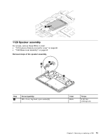
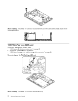
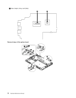
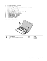
Loosen the screws in the alphabetical order as shown. Then remove the thermal fan assembly. 2 2f 2d 2a 2g 3 2e 2c 2b When you install the thermal fan assembly: • Always wear fingerstalls when handling the thermal fan assembly. Do not touch or hold any part of the thermal fan assembly with bare fingers. • Before you attach the thermal fan assembly to the computer, apply thermal grease, at an amount of 0.2 grams, on the part marked a as shown in the following illustrations. Either too much or too less application of grease can cause a thermal problem due to imperfect contact with a component. You should peel the thin film off from the rubbers marked b . a b • Do not touch the thermal grease. • Do not press, touch, or rotate the fan impeller. • Do not touch the fan inlet hole. • Do not twist or pull the cable of the thermal fan assembly. • Do not apply pressure on the top and bottom covers of the thermal fan assembly. • Do not press the heat pipe. Hold both sides of the heat pipe if you need to take the thermal fan assembly. • Do not shake or drop the thermal fan assembly. • Ensure that the fan connector is attached firmly. 1170 Keyboard bezel assembly and LCD unit For access, remove these FRUs in order: • "1010 Lenovo-OneLink-connector cover" on page 60 • "1020 Keyboard" on page 61 78 Hardware Maintenance Manual
-
 1
1 -
2
-
3
-
4
-
5
-
6
-
7
-
8
-
9
-
10
-
11
-
12
-
13
-
14
-
15
-
16
-
17
-
18
-
19
-
20
-
21
-
22
-
23
-
24
-
25
-
26
-
27
-
28
-
29
-
30
-
31
-
32
-
33
-
34
-
35
-
36
-
37
-
38
-
39
-
40
-
41
-
42
-
43
-
44
-
45
-
46
-
47
-
48
-
49
-
50
-
51
-
52
-
53
-
54
-
55
-
56
-
57
-
58
-
59
-
60
-
61
-
62
-
63
-
64
-
65
-
66
-
67
-
68
-
69
-
70
-
71
-
72
-
73
-
74
-
75
-
76
-
77
-
78
-
 79
79 -
 80
80 -
 81
81 -
 82
82 -
 83
83 -
 84
84 -
 85
85 -
 86
86 -
 87
87 -
 88
88 -
 89
89 -
90
-
91
-
92
-
93
-
94
-
95
-
96
-
97
-
98
-
99
-
100
-
101
-
102
 |
 |
