Lenovo ThinkPad i Series 1400 Hardware Maintenance Manual (August 1999) - Page 177
LCD Panel, LCD Cable and Inverter, There are adhesive tape attached to the micro
 |
View all Lenovo ThinkPad i Series 1400 manuals
Add to My Manuals
Save this manual to your list of manuals |
Page 177 highlights
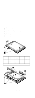
3 2 1 Step Size (Quantity) Head & Color Torque Memo 1 M2 x 4L Pan 2.0 (2) head, kgf-cm silver Note: Make sure you use the correct screw for replacement. 5 4 Note: There are adhesive tape attached to the microphone cable assembly. Do not forget to put them back when reinstalling. LCD Panel, LCD Cable and Inverter "Battery Assembly" on page 142 "Keyboard" on page 145 "Processor Thermal Plate" on page 147 "RTC Battery, Processor EMI Shield and Hard Disk Drive" on page 148 "LCD Assembly" on page 151 "LCD Front Cover (12.1-inch)" on page 167 ThinkPad i Series 1400 (Part II) 169
-
 1
1 -
2
-
3
-
4
-
5
-
6
-
7
-
8
-
9
-
10
-
11
-
12
-
13
-
14
-
15
-
16
-
17
-
18
-
19
-
20
-
21
-
22
-
23
-
24
-
25
-
26
-
27
-
28
-
29
-
30
-
31
-
32
-
33
-
34
-
35
-
36
-
37
-
38
-
39
-
40
-
41
-
42
-
43
-
44
-
45
-
46
-
47
-
48
-
49
-
50
-
51
-
52
-
53
-
54
-
55
-
56
-
57
-
58
-
59
-
60
-
61
-
62
-
63
-
64
-
65
-
66
-
67
-
68
-
69
-
70
-
71
-
72
-
73
-
74
-
75
-
76
-
77
-
78
-
79
-
80
-
81
-
82
-
83
-
84
-
85
-
86
-
87
-
88
-
89
-
90
-
91
-
92
-
93
-
94
-
95
-
96
-
97
-
98
-
99
-
100
-
101
-
102
-
103
-
104
-
105
-
106
-
107
-
108
-
109
-
110
-
111
-
112
-
113
-
114
-
115
-
116
-
117
-
118
-
119
-
120
-
121
-
122
-
123
-
124
-
125
-
126
-
127
-
128
-
129
-
130
-
131
-
132
-
133
-
134
-
135
-
136
-
137
-
138
-
139
-
140
-
141
-
142
-
143
-
144
-
145
-
146
-
147
-
148
-
149
-
150
-
151
-
152
-
153
-
154
-
155
-
156
-
157
-
158
-
159
-
160
-
161
-
162
-
163
-
164
-
165
-
166
-
167
-
168
-
169
-
170
-
171
-
 172
172 -
 173
173 -
 174
174 -
 175
175 -
 176
176 -
 177
177 -
 178
178 -
 179
179 -
 180
180 -
 181
181 -
 182
182 -
183
-
184
-
185
-
186
-
187
-
188
-
189
-
190
-
191
-
192
-
193
-
194
-
195
-
196
-
197
-
198
-
199
-
200
-
201
-
202
-
203
-
204
 |
 |

1
3
2
4
5
Note:
There are adhesive tape attached to the micro-
phone cable assembly. Do not forget to put them
back when reinstalling.
LCD Panel, LCD Cable and Inverter
±
“Battery Assembly” on page
142
±
“Keyboard” on page
145
±
“Processor Thermal Plate” on page
147
±
“RTC Battery, Processor EMI Shield and Hard Disk
Drive” on page
148
±
“LCD Assembly” on page
151
±
“LCD Front Cover (12.1-inch)” on page
167
Step
Size
(Quan-
tity)
Head &
Color
Torque
Memo
1
M2 x 4L
(2)
Pan
head,
silver
2.0
kgf-cm
Note:
Make sure you use the correct screw for replacement.
ThinkPad i Series 1400 (Part II)
169