Lenovo ThinkServer RD330 Hardware Maintenance Manual - ThinkServer RD330 - Page 168
Connect the power cable, module cable, and the SATA signal cable for the optical drive.
 |
View all Lenovo ThinkServer RD330 manuals
Add to My Manuals
Save this manual to your list of manuals |
Page 168 highlights
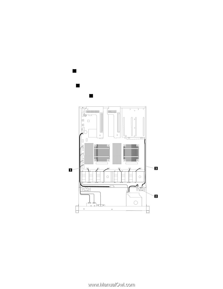
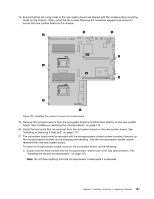
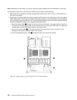
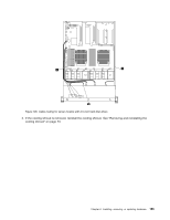
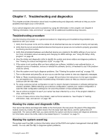
Note: Depending on the model, your server might look slightly different from the illustrations in this topic. To reinstall the server cover and reconnect cables to your server, do the following: 1. Ensure that all components have been reassembled correctly and that no tools or loose screws are left inside your server. 2. Ensure that all internal cables are routed correctly and secured by any cable clips or ties in the server. Keep cables clear of the hinges and sides of the server chassis to avoid interference with reinstalling the cooling shroud and the server cover. The following illustrations show the cable routing for the two chassis configurations based on the supported hard disk drives. • Route the signal cables 1 through the left inner side of the chassis. The signal cables include the mini-SAS to mini-SAS signal cable, the front panel cable, the front panel USB cable, the diagnostic module cable, and the SATA signal cable for the optical drive. • Connect the power cable 2 for the optical drive to the optical drive power connector on the backplane and properly route the cable in the chassis. • Route the backplane power cable 3 through the right inner side of the chassis. Figure 107. Cable routing for server models with 3.5-inch hard disk drives 154 ThinkServer RD330 Hardware Maintenance Manual
-
 1
1 -
2
-
3
-
4
-
5
-
6
-
7
-
8
-
9
-
10
-
11
-
12
-
13
-
14
-
15
-
16
-
17
-
18
-
19
-
20
-
21
-
22
-
23
-
24
-
25
-
26
-
27
-
28
-
29
-
30
-
31
-
32
-
33
-
34
-
35
-
36
-
37
-
38
-
39
-
40
-
41
-
42
-
43
-
44
-
45
-
46
-
47
-
48
-
49
-
50
-
51
-
52
-
53
-
54
-
55
-
56
-
57
-
58
-
59
-
60
-
61
-
62
-
63
-
64
-
65
-
66
-
67
-
68
-
69
-
70
-
71
-
72
-
73
-
74
-
75
-
76
-
77
-
78
-
79
-
80
-
81
-
82
-
83
-
84
-
85
-
86
-
87
-
88
-
89
-
90
-
91
-
92
-
93
-
94
-
95
-
96
-
97
-
98
-
99
-
100
-
101
-
102
-
103
-
104
-
105
-
106
-
107
-
108
-
109
-
110
-
111
-
112
-
113
-
114
-
115
-
116
-
117
-
118
-
119
-
120
-
121
-
122
-
123
-
124
-
125
-
126
-
127
-
128
-
129
-
130
-
131
-
132
-
133
-
134
-
135
-
136
-
137
-
138
-
139
-
140
-
141
-
142
-
143
-
144
-
145
-
146
-
147
-
148
-
149
-
150
-
151
-
152
-
153
-
154
-
155
-
156
-
157
-
158
-
159
-
160
-
161
-
162
-
 163
163 -
 164
164 -
 165
165 -
 166
166 -
 167
167 -
 168
168 -
 169
169 -
 170
170 -
 171
171 -
 172
172 -
 173
173 -
174
-
175
-
176
-
177
-
178
-
179
-
180
-
181
-
182
-
183
-
184
-
185
-
186
-
187
-
188
-
189
-
190
-
191
-
192
-
193
-
194
-
195
-
196
 |
 |