Lenovo ThinkServer RD330 (German) Installation and User Guide - Page 98
In der folgenden Abbildung sind die Positionen aller Speichersteckplätze auf einer Systemplatine dargestellt
 |
View all Lenovo ThinkServer RD330 manuals
Add to My Manuals
Save this manual to your list of manuals |
Page 98 highlights
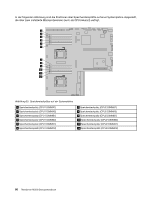
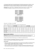
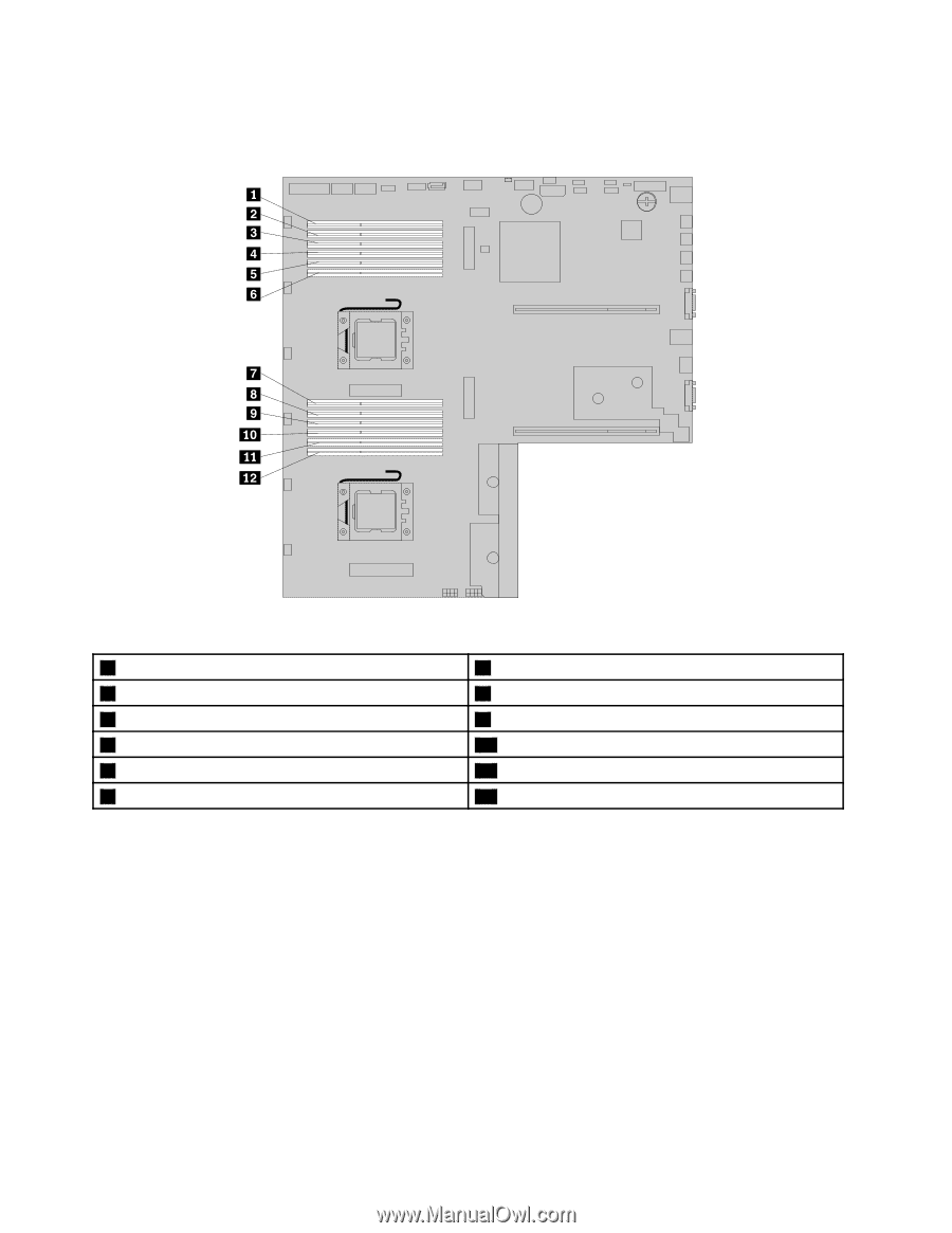
In der folgenden Abbildung sind die Positionen aller Speichersteckplätze auf einer Systemplatine dargestellt, die über zwei installierte Mikroprozessoren (auch als CPU bekannt) verfügt. Abbildung 33. Speichersteckplätze auf der Systemplatine 1 Speichersteckplatz (CPU1 DIMMA1) 2 Speichersteckplatz (CPU1 DIMMA2) 3 Speichersteckplatz (CPU1 DIMMB1) 4 Speichersteckplatz (CPU1 DIMMB2) 5 Speichersteckplatz (CPU1 DIMMC1) 6 Speichersteckplatz (CPU1 DIMMC2) 7 Speichersteckplatz (CPU2 DIMMA1) 8 Speichersteckplatz (CPU2 DIMMA2) 9 Speichersteckplatz (CPU2 DIMMB1) 10 Speichersteckplatz (CPU2 DIMMB2) 11 Speichersteckplatz (CPU2 DIMMC1) 12 Speichersteckplatz (CPU2 DIMMC2) 86 ThinkServer RD330 Benutzerhandbuch
-
 1
1 -
2
-
3
-
4
-
5
-
6
-
7
-
8
-
9
-
10
-
11
-
12
-
13
-
14
-
15
-
16
-
17
-
18
-
19
-
20
-
21
-
22
-
23
-
24
-
25
-
26
-
27
-
28
-
29
-
30
-
31
-
32
-
33
-
34
-
35
-
36
-
37
-
38
-
39
-
40
-
41
-
42
-
43
-
44
-
45
-
46
-
47
-
48
-
49
-
50
-
51
-
52
-
53
-
54
-
55
-
56
-
57
-
58
-
59
-
60
-
61
-
62
-
63
-
64
-
65
-
66
-
67
-
68
-
69
-
70
-
71
-
72
-
73
-
74
-
75
-
76
-
77
-
78
-
79
-
80
-
81
-
82
-
83
-
84
-
85
-
86
-
87
-
88
-
89
-
90
-
91
-
92
-
 93
93 -
 94
94 -
 95
95 -
 96
96 -
 97
97 -
 98
98 -
 99
99 -
 100
100 -
 101
101 -
 102
102 -
 103
103 -
104
-
105
-
106
-
107
-
108
-
109
-
110
-
111
-
112
-
113
-
114
-
115
-
116
-
117
-
118
-
119
-
120
-
121
-
122
-
123
-
124
-
125
-
126
-
127
-
128
-
129
-
130
-
131
-
132
-
133
-
134
-
135
-
136
-
137
-
138
-
139
-
140
-
141
-
142
-
143
-
144
-
145
-
146
-
147
-
148
-
149
-
150
-
151
-
152
-
153
-
154
-
155
-
156
-
157
-
158
-
159
-
160
-
161
-
162
-
163
-
164
-
165
-
166
-
167
-
168
-
169
-
170
-
171
-
172
-
173
-
174
-
175
-
176
-
177
-
178
-
179
-
180
-
181
-
182
-
183
-
184
-
185
-
186
-
187
-
188
-
189
-
190
-
191
-
192
-
193
-
194
-
195
-
196
-
197
-
198
-
199
-
200
-
201
-
202
-
203
-
204
-
205
-
206
-
207
-
208
-
209
-
210
-
211
-
212
 |
 |
In der folgenden Abbildung sind die Positionen aller Speichersteckplätze auf einer Systemplatine dargestellt,
die über zwei installierte Mikroprozessoren (auch als CPU bekannt) verfügt.
Abbildung 33. Speichersteckplätze auf der Systemplatine
1
Speichersteckplatz (CPU1 DIMMA1)
7
Speichersteckplatz (CPU2 DIMMA1)
2
Speichersteckplatz (CPU1 DIMMA2)
8
Speichersteckplatz (CPU2 DIMMA2)
3
Speichersteckplatz (CPU1 DIMMB1)
9
Speichersteckplatz (CPU2 DIMMB1)
4
Speichersteckplatz (CPU1 DIMMB2)
10
Speichersteckplatz (CPU2 DIMMB2)
5
Speichersteckplatz (CPU1 DIMMC1)
11
Speichersteckplatz (CPU2 DIMMC1)
6
Speichersteckplatz (CPU1 DIMMC2)
12
Speichersteckplatz (CPU2 DIMMC2)
86
ThinkServer RD330 Benutzerhandbuch