Lenovo ThinkServer RD330 (English) Installation and User Guide - Page 43
System board components, Refer to the following topics for information about the connector locations
 |
View all Lenovo ThinkServer RD330 manuals
Add to My Manuals
Save this manual to your list of manuals |
Page 43 highlights
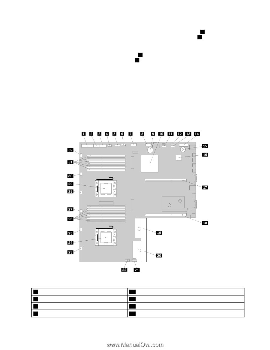
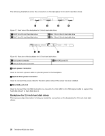
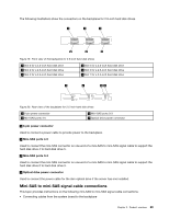
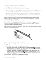
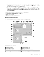
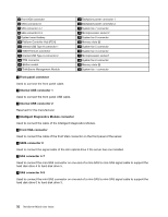
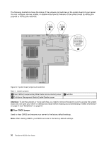
1. Use one mini-SAS to mini-SAS signal cable. Connect the mini-SAS connector 1 on one end of the cable to the port 0 on the RAID card. Then, connect the mini-SAS connector 2 on the other end of the cable to the mini-SAS ports 0-3 on the backplane. 2. If your server has more than four hard disk drives installed, use the other mini-SAS to mini-SAS signal cable. Connect the mini-SAS connector 3 on one end of the cable to the port 1 on the RAID card. Then, connect the mini-SAS connector 4 on the other end of the cable to the mini-SAS ports 4-5 on the backplane. Refer to the following topics for information about the connector locations: • "Hot-swap hard disk drive backplane" on page 27 • "RAID card" on page 25 • "System board components" on page 31 System board components The following illustration shows the component locations on the system board. Figure 22. System board components 1 Front panel connector 2 Internal USB connector 1 3 Internal USB connector 2 4 Intelligent Diagnostics Module connector 17 Riser card assembly 1 slot 18 Riser card assembly 2 slot 19 Redundant power supply connector 1 20 Redundant power supply connector 2 Chapter 3. Product overview 31
-
 1
1 -
2
-
3
-
4
-
5
-
6
-
7
-
8
-
9
-
10
-
11
-
12
-
13
-
14
-
15
-
16
-
17
-
18
-
19
-
20
-
21
-
22
-
23
-
24
-
25
-
26
-
27
-
28
-
29
-
30
-
31
-
32
-
33
-
34
-
35
-
36
-
37
-
 38
38 -
 39
39 -
 40
40 -
 41
41 -
 42
42 -
 43
43 -
 44
44 -
 45
45 -
 46
46 -
 47
47 -
 48
48 -
49
-
50
-
51
-
52
-
53
-
54
-
55
-
56
-
57
-
58
-
59
-
60
-
61
-
62
-
63
-
64
-
65
-
66
-
67
-
68
-
69
-
70
-
71
-
72
-
73
-
74
-
75
-
76
-
77
-
78
-
79
-
80
-
81
-
82
-
83
-
84
-
85
-
86
-
87
-
88
-
89
-
90
-
91
-
92
-
93
-
94
-
95
-
96
-
97
-
98
-
99
-
100
-
101
-
102
-
103
-
104
-
105
-
106
-
107
-
108
-
109
-
110
-
111
-
112
-
113
-
114
-
115
-
116
-
117
-
118
-
119
-
120
-
121
-
122
-
123
-
124
-
125
-
126
-
127
-
128
-
129
-
130
-
131
-
132
-
133
-
134
-
135
-
136
-
137
-
138
-
139
-
140
-
141
-
142
-
143
-
144
-
145
-
146
-
147
-
148
-
149
-
150
-
151
-
152
-
153
-
154
-
155
-
156
-
157
-
158
-
159
-
160
-
161
-
162
-
163
-
164
-
165
-
166
-
167
-
168
-
169
-
170
-
171
-
172
-
173
-
174
-
175
-
176
-
177
-
178
-
179
-
180
-
181
-
182
-
183
-
184
-
185
-
186
-
187
-
188
-
189
-
190
-
191
-
192
 |
 |