Lenovo V370 Lenovo V370 Hardware Maintenance Manual - Page 57
Fan assembly and Heat Sink assembly
 |
View all Lenovo V370 manuals
Add to My Manuals
Save this manual to your list of manuals |
Page 57 highlights
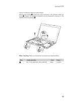
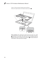
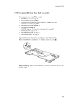
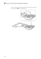
Lenovo V370 1110 Fan assembly and Heat Sink assembly For access, remove these FRUs in order: •• "1010 Battery pack" on page 34 •• "1020 Dummy card" on page 35 •• "1030 Hard disk drive(HDD)/Memory/Mini PCI Express Card slot compartment cover" on page 36 •• "1040 Hard disk drive" on page 37 •• "1050 DIMM" on page 38 •• "1060 PCI Express Mini Card for wireless LAN" on page 39 •• "1070 Keyboard" on page 41 •• "1080 Keyboard bezel" on page 43 •• "1090 System board" on page 48 Figure 12. Removal steps of fan assembly and heat sink assembly Note: Detach the fan connector in the direction shown by arrow 1. 1 When installing: Make sure that the fan connector is attached firmly to the system board. 53
-
 1
1 -
2
-
3
-
4
-
5
-
6
-
7
-
8
-
9
-
10
-
11
-
12
-
13
-
14
-
15
-
16
-
17
-
18
-
19
-
20
-
21
-
22
-
23
-
24
-
25
-
26
-
27
-
28
-
29
-
30
-
31
-
32
-
33
-
34
-
35
-
36
-
37
-
38
-
39
-
40
-
41
-
42
-
43
-
44
-
45
-
46
-
47
-
48
-
49
-
50
-
51
-
 52
52 -
 53
53 -
 54
54 -
 55
55 -
 56
56 -
 57
57 -
 58
58 -
 59
59 -
 60
60 -
 61
61 -
 62
62 -
63
-
64
-
65
-
66
-
67
-
68
-
69
-
70
-
71
-
72
-
73
-
74
-
75
-
76
-
77
-
78
-
79
-
80
-
81
-
82
-
83
-
84
-
85
-
86
-
87
 |
 |

53
Lenovo V370
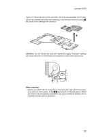
1110 Fan assembly and Heat Sink assembly
For access, remove these FRUs in order:
•
“1010 Battery pack” on page 34
•
“1020 Dummy card” on page 35
•
“1030 Hard disk drive(HDD)/Memory/Mini PCI Express Card slot
compartment cover” on page 36
•
“1040 Hard disk drive” on page 37
•
“1050 DIMM” on page 38
•
“1060 PCI Express Mini Card for wireless LAN” on page 39
•
“1070 Keyboard” on page 41
•
“1080 Keyboard bezel” on page 43
•
“1090 System board” on page 48
Figure 12. Removal steps of fan assembly and heat sink assembly
Note:
Detach the fan connector in the direction shown by arrow
1
.
1
When installing:
Make sure that the fan connector is attached firmly to the
system board.